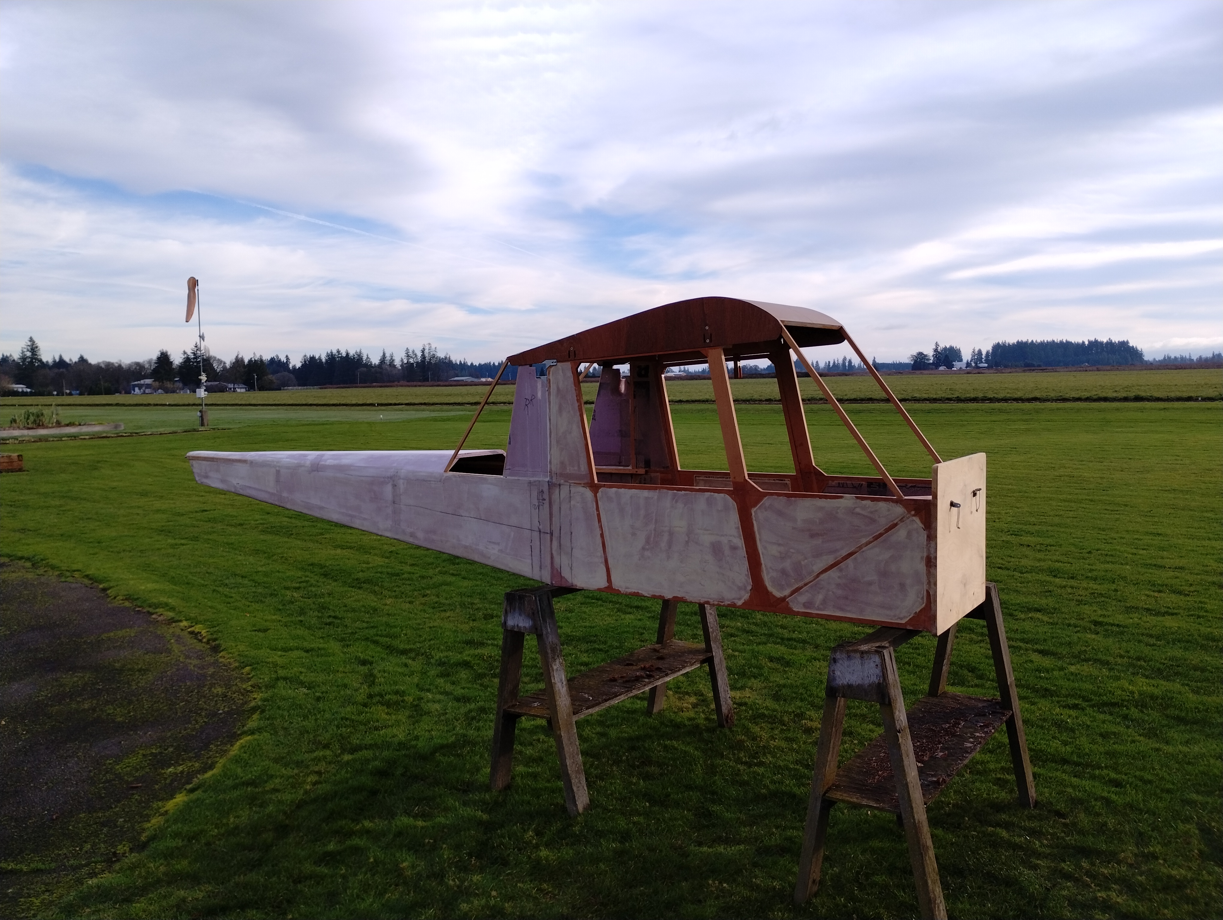
The cabin is as done as it is going to get for now; I'm deferring the cowl deck ("boot cowl" if you're a Brit/ Aussie/ Kiwi) so I have better access to layout the controls installation. So onto the "Empennage" or as I call it, the tail cone.
The lumber ripping stage took place earlier on, leaving me with 3/4"x3/4"x10'
strips of hemlock for longeron.
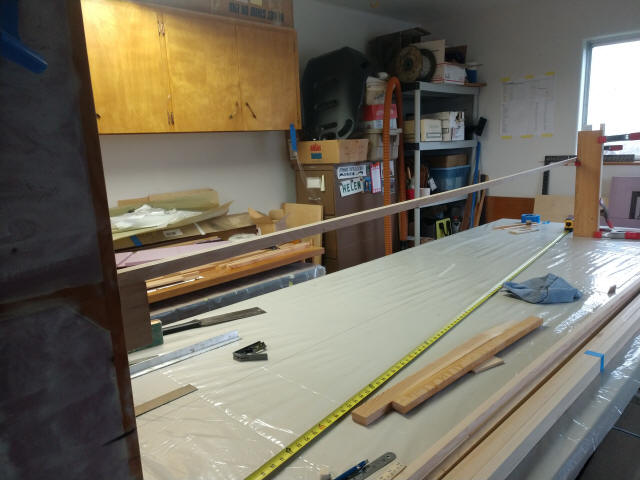
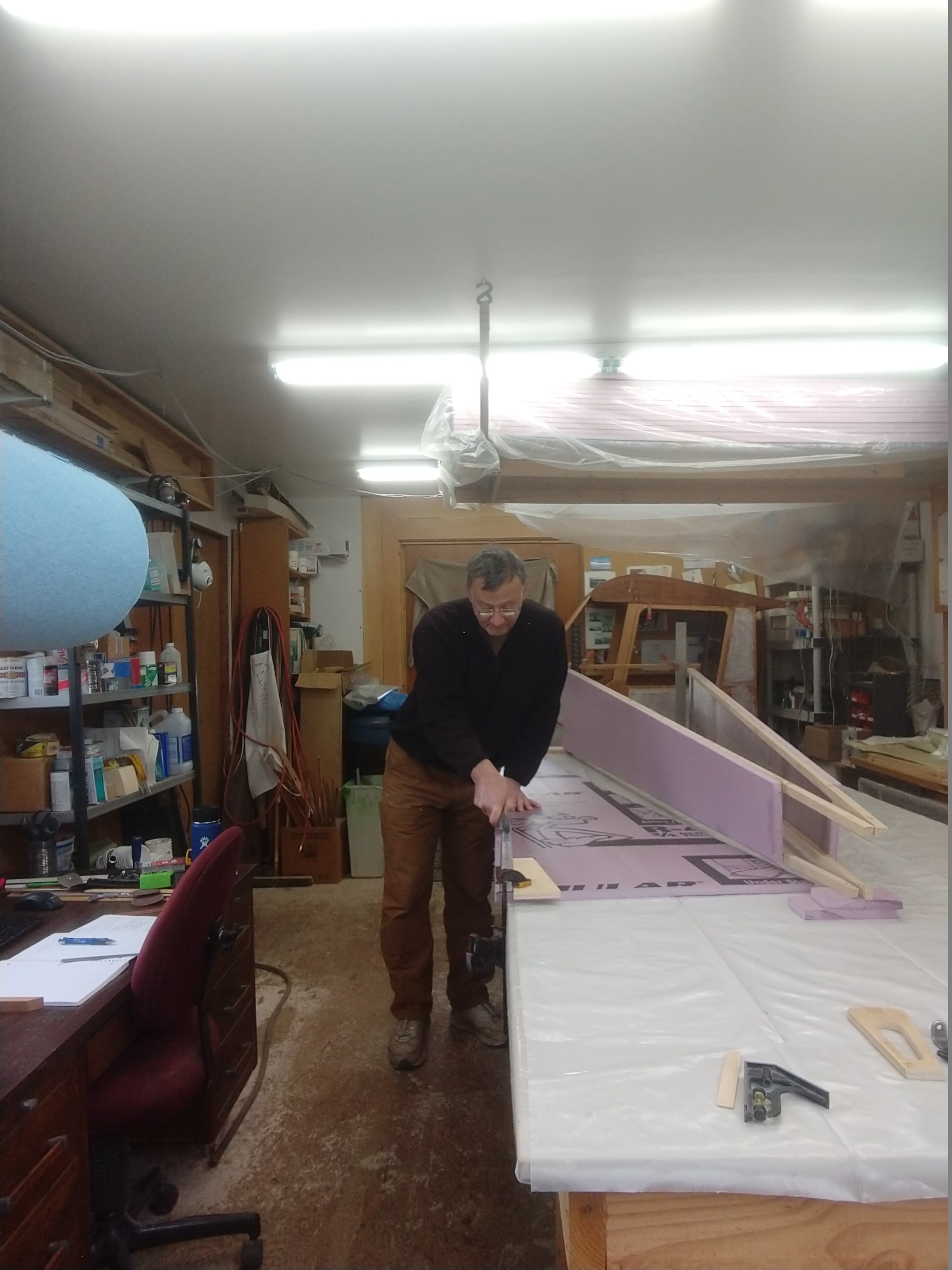
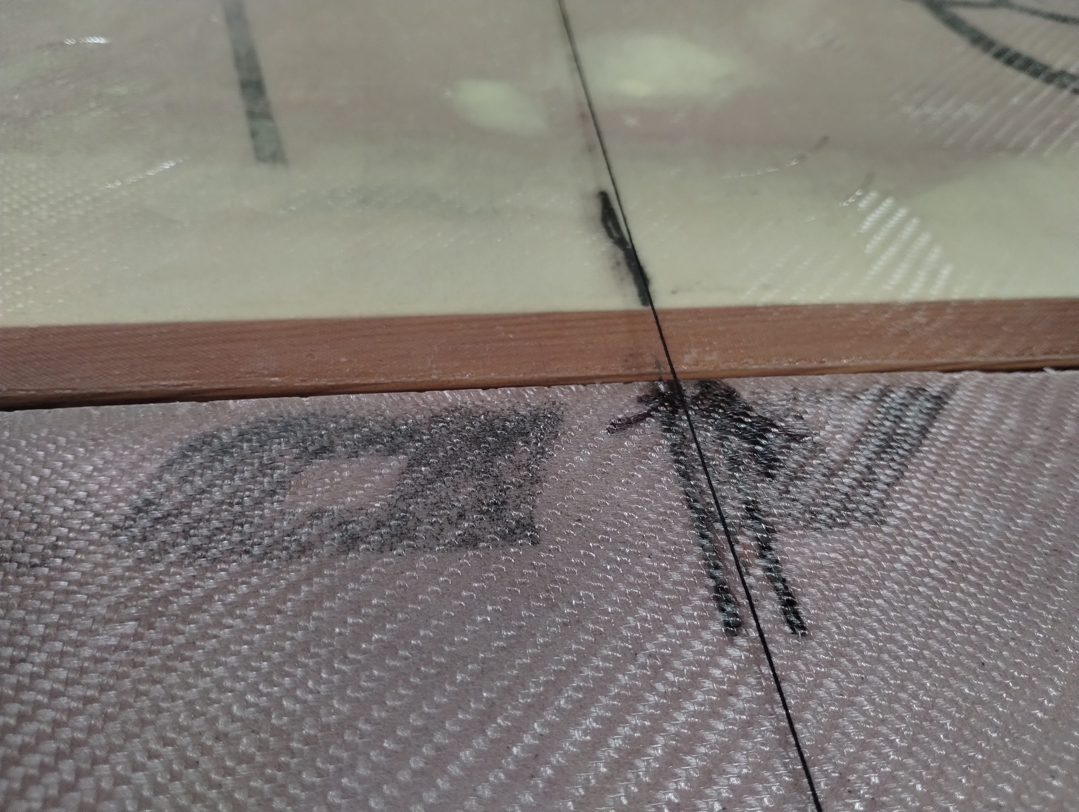
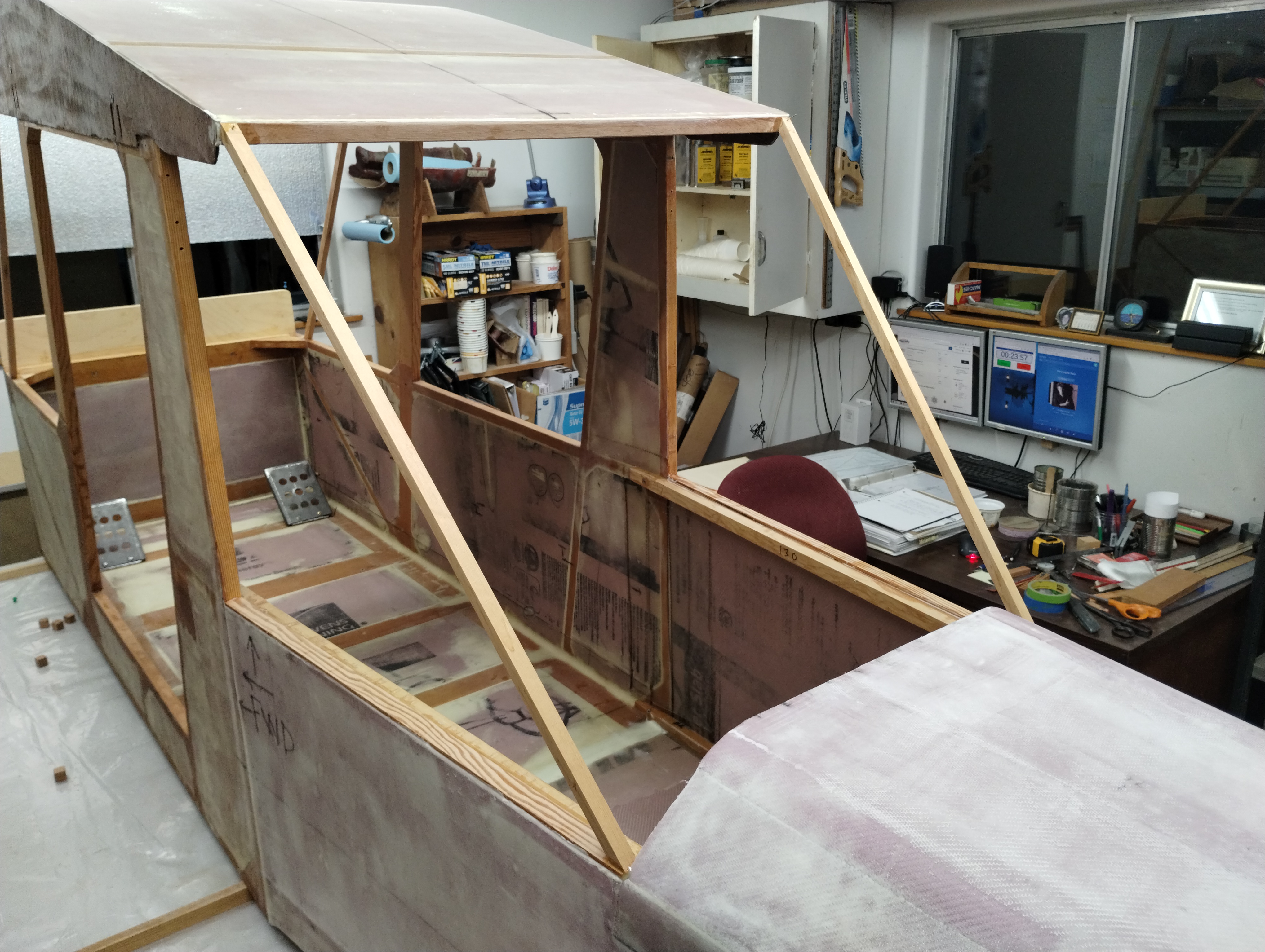
Set your cabin on the table and get it PERFECTLY level in pitch and roll. Mark the center of the floor at the firewall and the aft most cross member. Use a thin thread to make a straight line away from the cabin and right off the end of the table. Suspend the thread with a block so it doesn't touch anything to disturb your coming alignment steps.
This shows the rough longeron sitting on a prop board clamped inside the
cabin wall. The other end is on the jig at the same height above the flat &
square table.
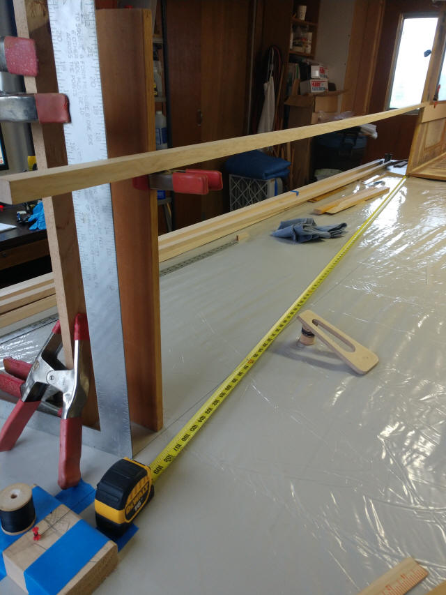
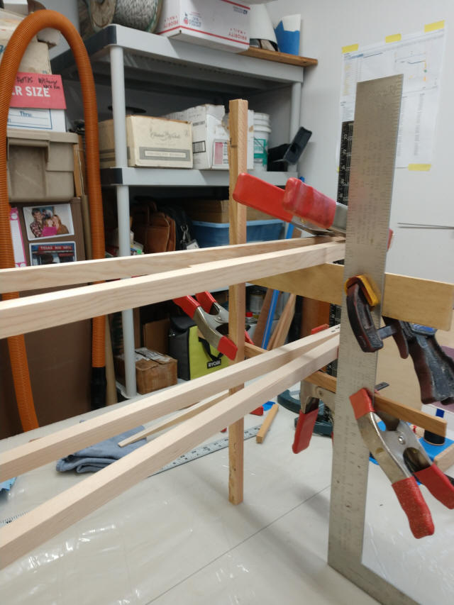
This is the height adjustment jig; just some boards clamped together with
spring clamps. Several things to notice here;
* The square is the elevation control above the table surface. What we're
matching here is the height of the bottom edge aligned with the bottom of the
upper cabin longeron. The base of the square is barely touching the thread
giving perfect alignment with the center of the cabin. You can measure over from
the vertical edge of the square to place the longeron in any relation to the
cabin center.
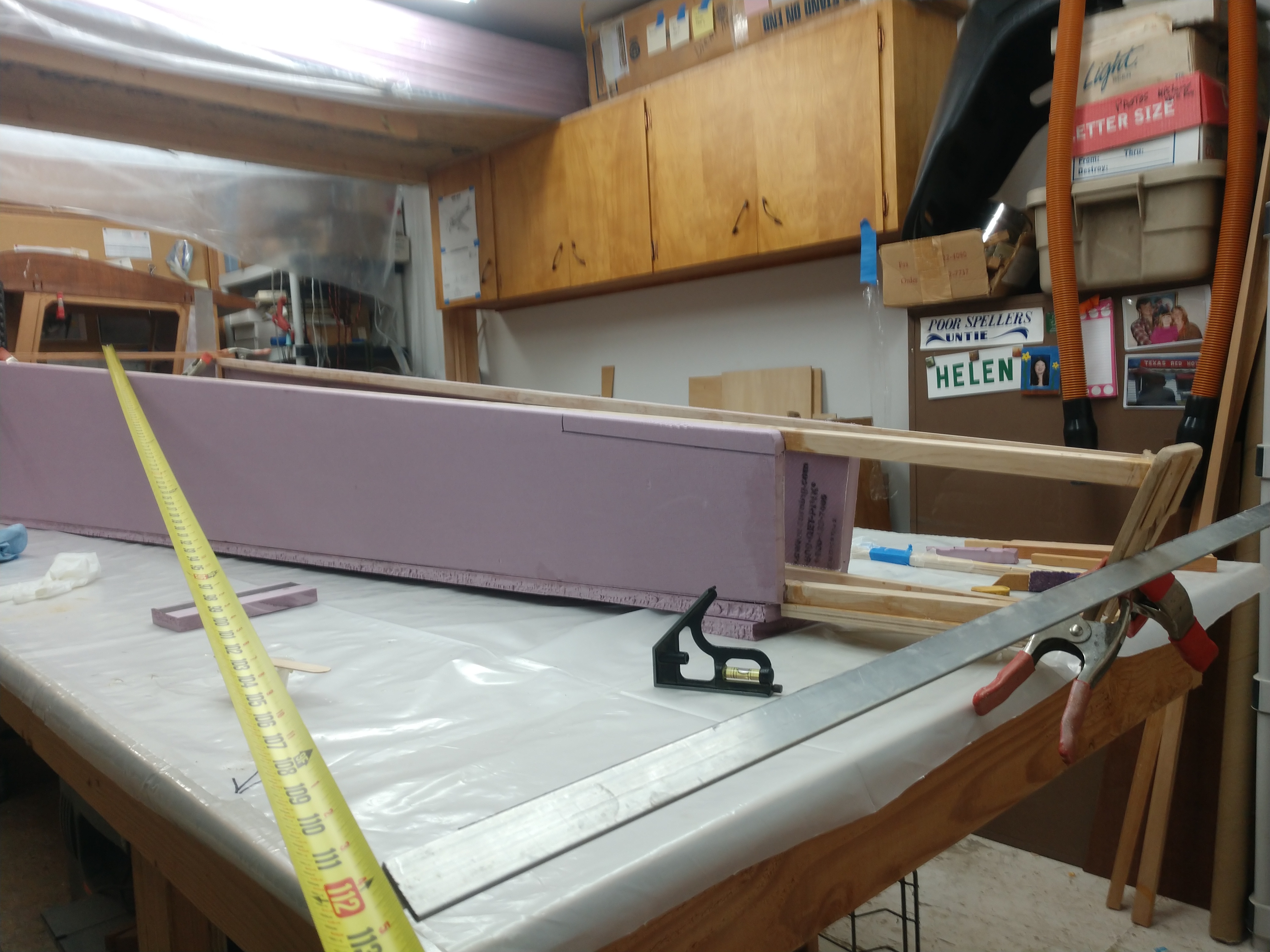
* Tape measure is set for proper longeron length: upper longeron so 109" aft of
the cabin post
* Guide block keeps the straight edge string from contacting anything
* The tail plate is there just to make it easier to see the guide thread
Use a straight edge (I used some 3/4" scrap stock) touching the inside cabin wall to draw a line on top of the longeron. Make the aft part of the line run off the longeron on the cabin wall side a bit more than 3" behind the forward end of the board to minimize your waste.
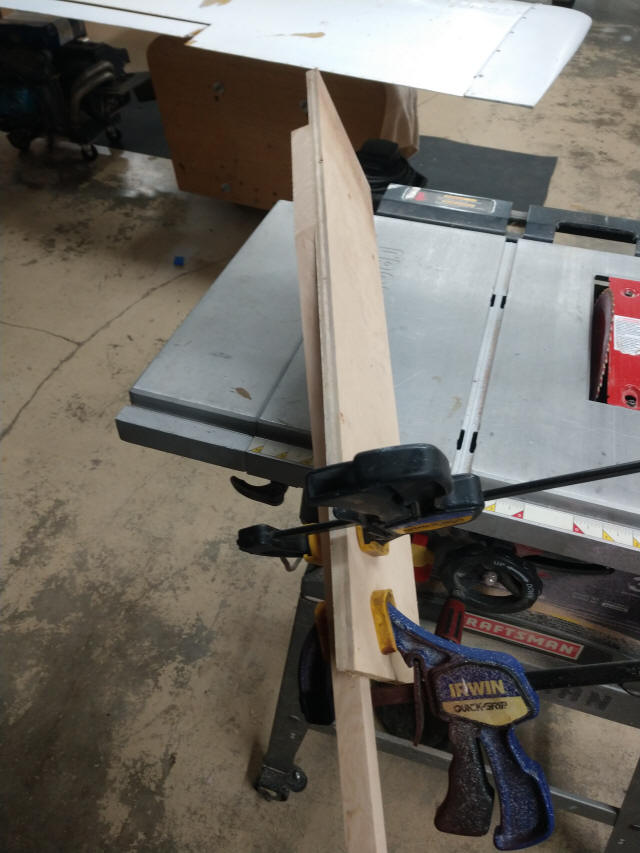
To cut the tapers, run a piece of plywood to some width (I used something
about 6" but it doesn't really matter) on
the table saw to square up the cut edge. DON'T move the fence. Next, clamp the cut line
very exactly to the
edge you just cut on the plywood. Push them both through. Perfectly aligned
taper to the cut line you marked in the step above...
Tip: put a scrap 3/4" thick board [matching the longeron thickness] on table, adjacent to the fence
so your guide board and longeron stock runs through flat & level. This was my
first proof-of-concept pass and I DIDN'T have the "leveling block" in place; you
can see the slight angle on the cut in this photo...
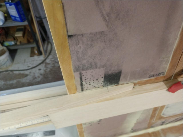
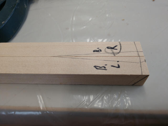
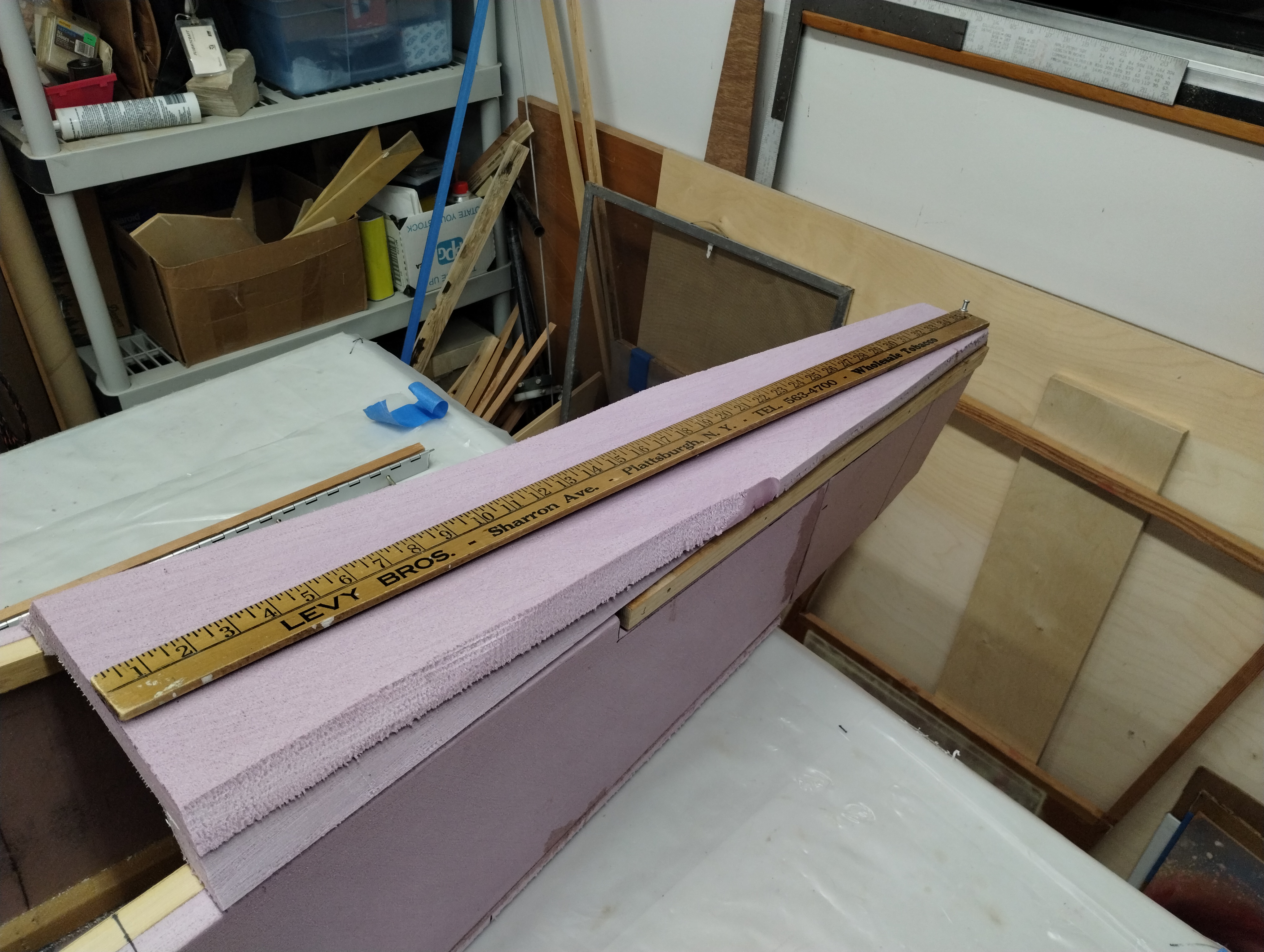
This shows the resulting taper fit. I'm happy with this. Note the 3" forward
pencil mark shows what gets trimmed off later as excess.
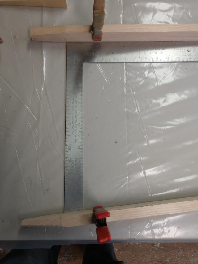
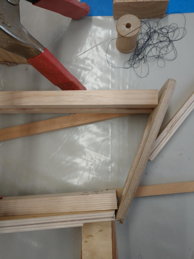
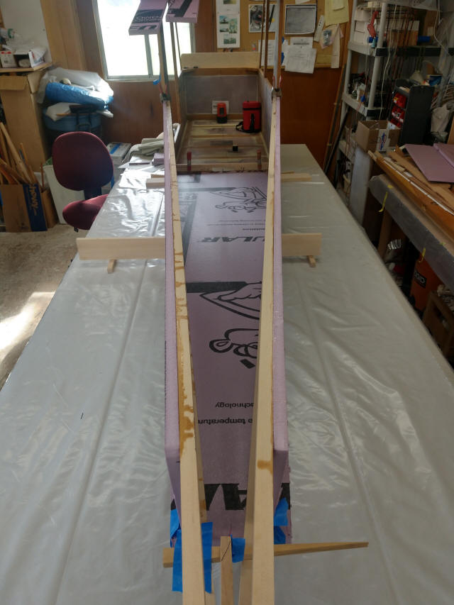
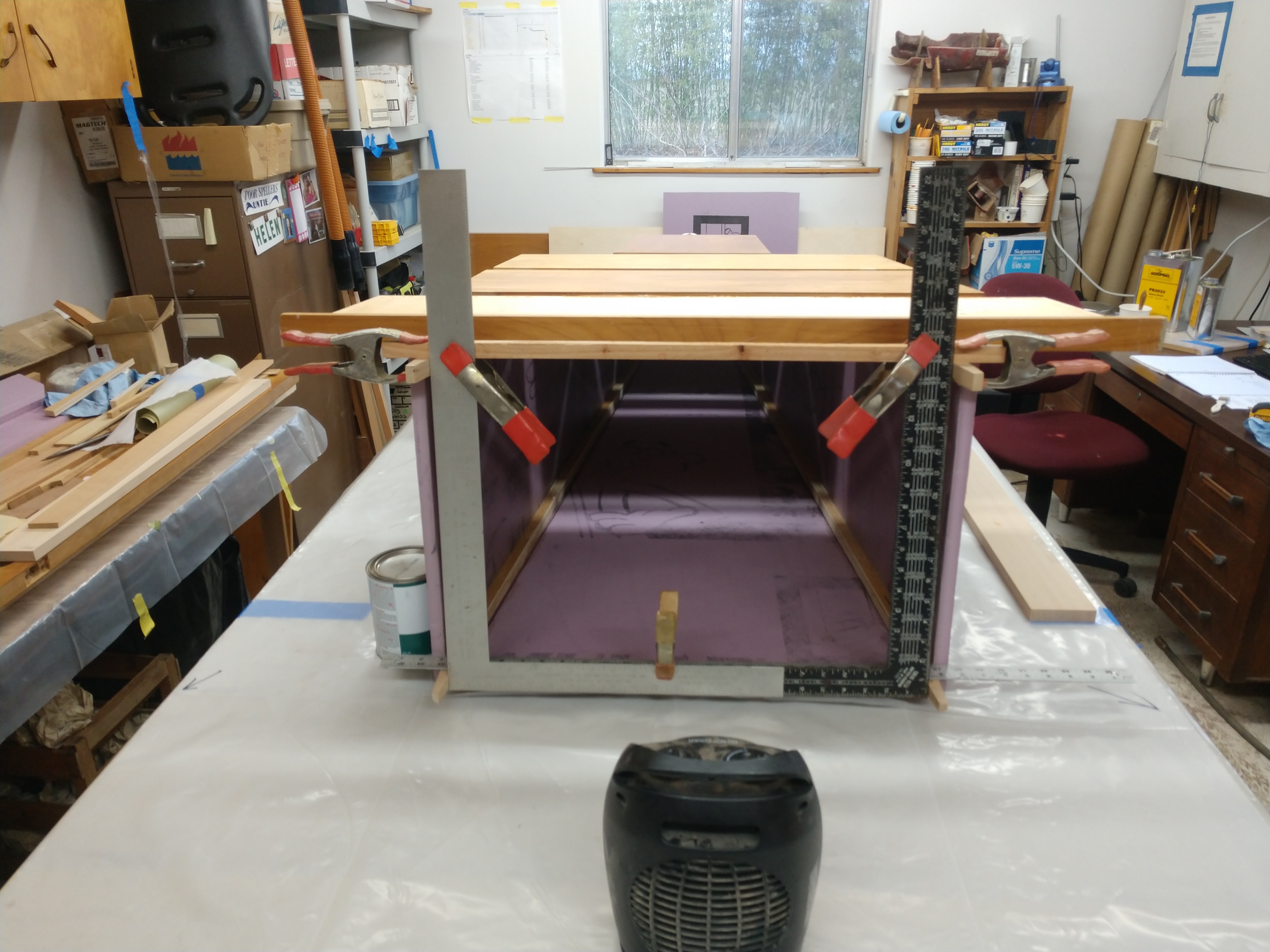
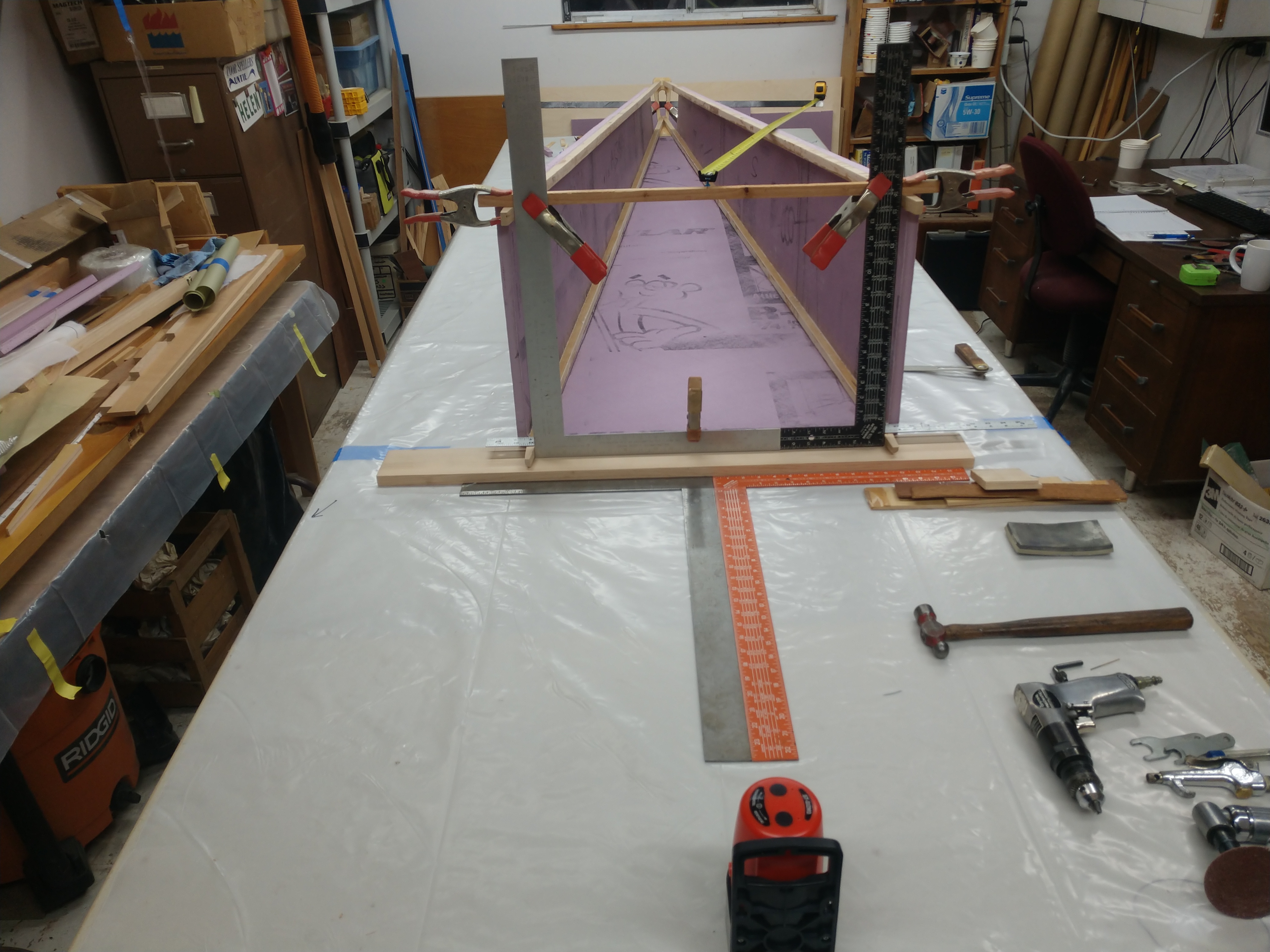
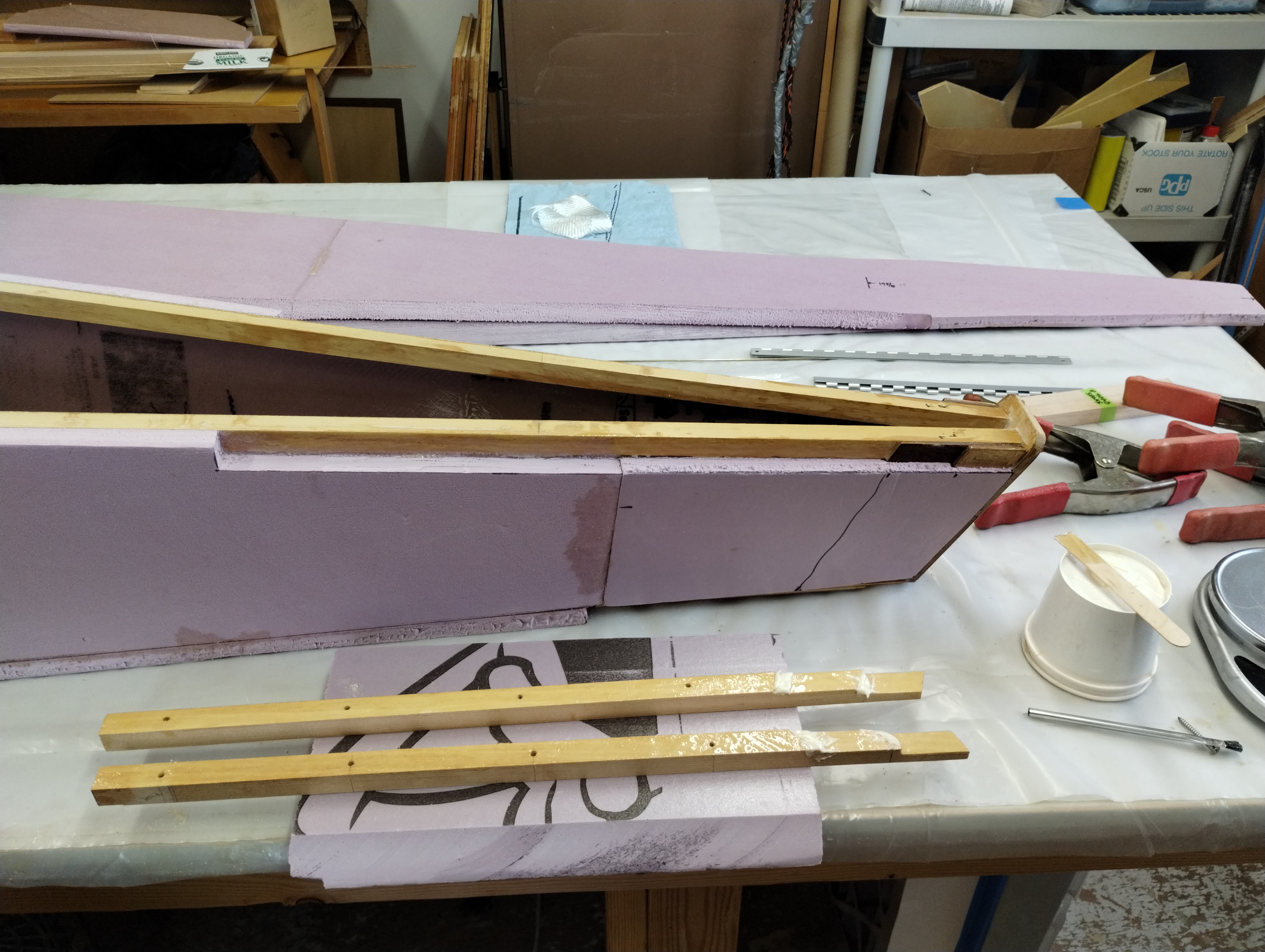
Now to taper and bevel the stern ends. The cabin-end tapers are marked on the 3" line that gets glued inside the cabin. The square replicates the aft-most upright cabin structural post. The upper longeron sits above the square and the lower longeron crosses at the 15 1/4" point as it will later. Spring clamps keep the left & right side members aligned.
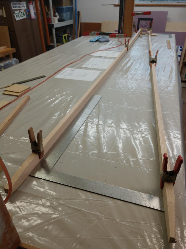
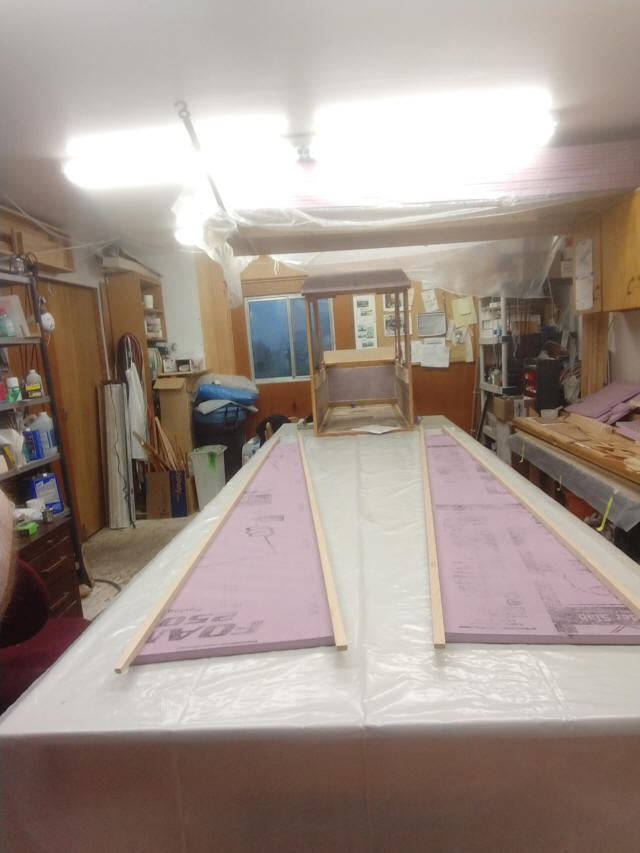
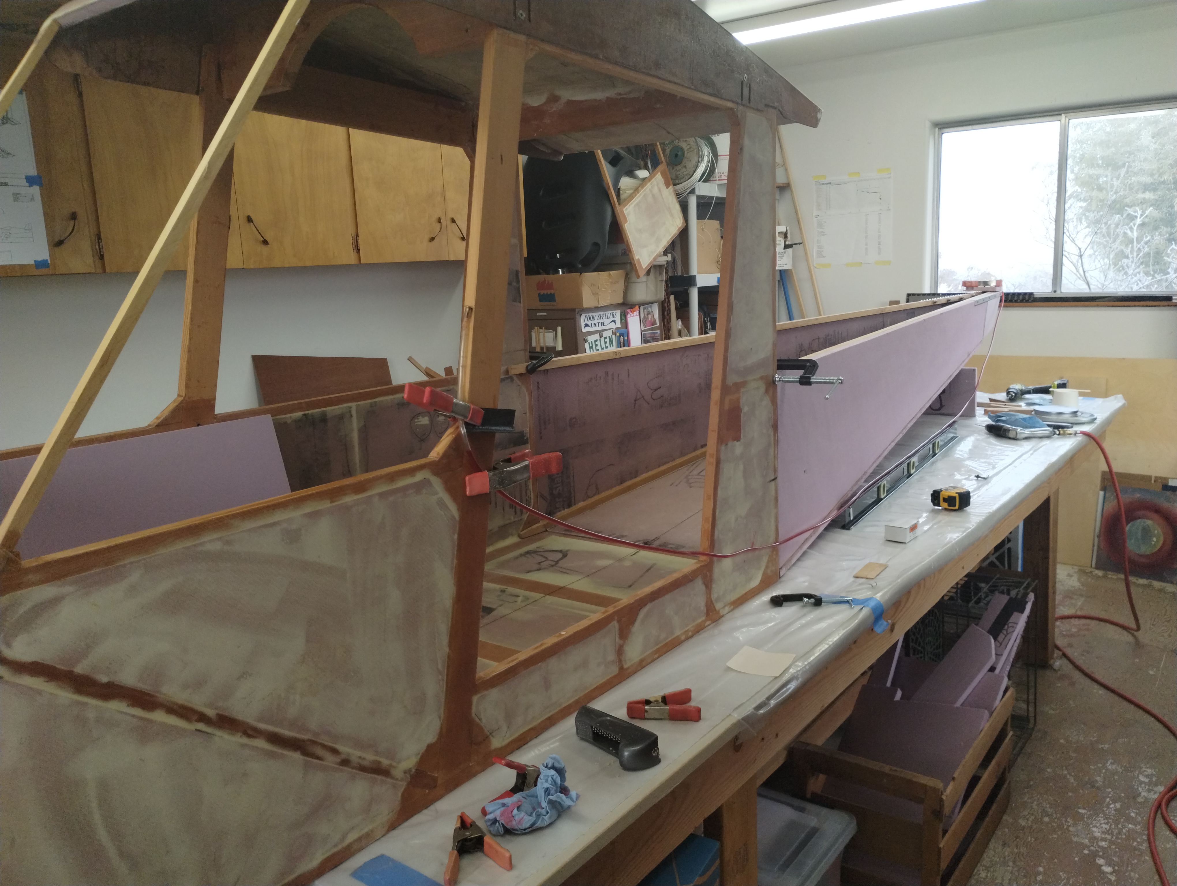
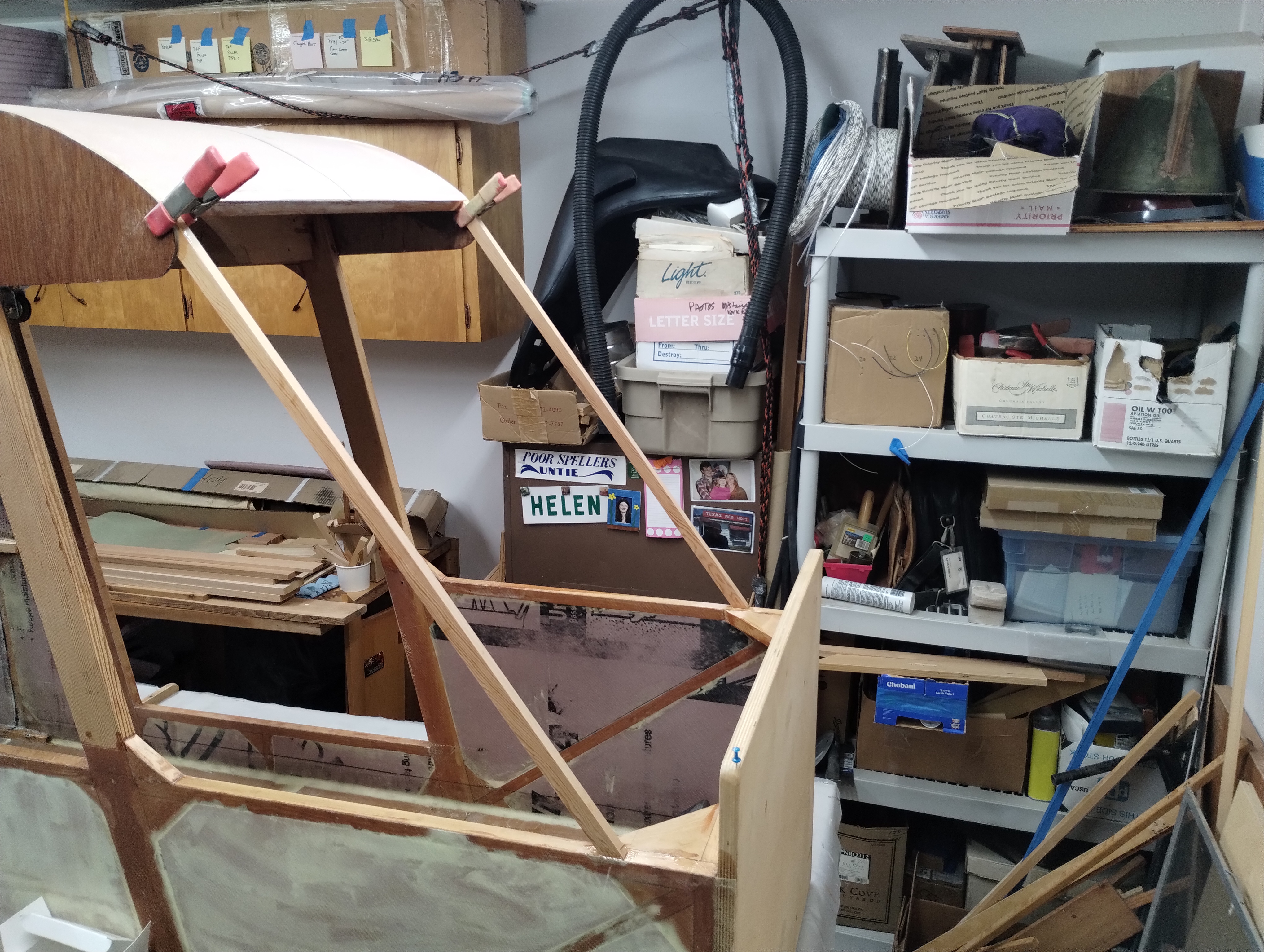
This is the "whole table view" of the parts laid out. The vertical fixture
allowed marking the forward tapers. The red snake is a water level. Ignore them both for now.
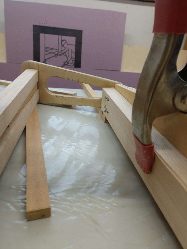
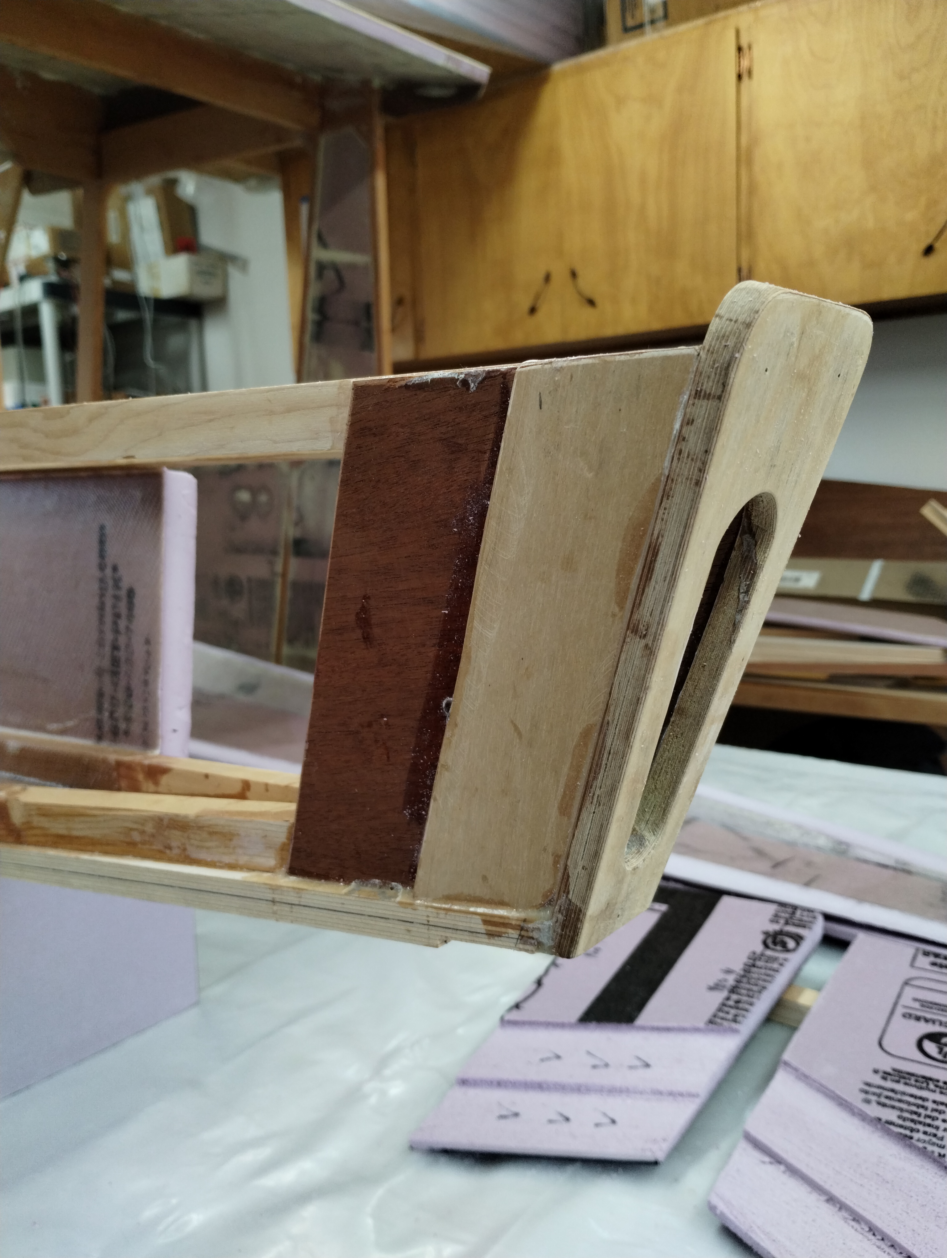
Close-up view of the longeron aft-end in rough position landing on the tail
plate, DWG82. Yes, there is some chipping of the top layer of plywood. I figure
it's ok as there are 19 other layers in this part.
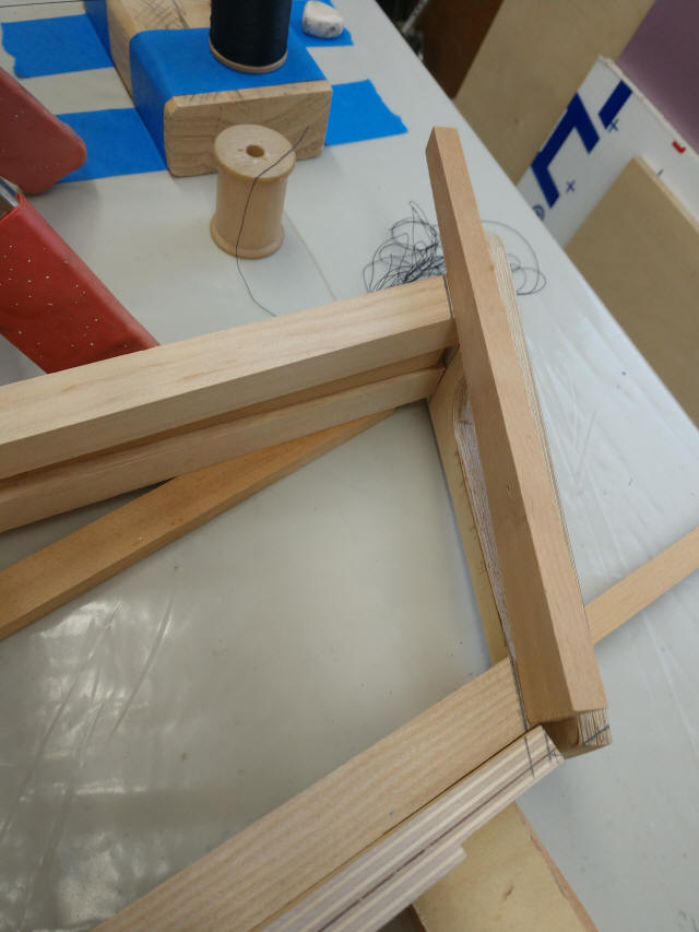
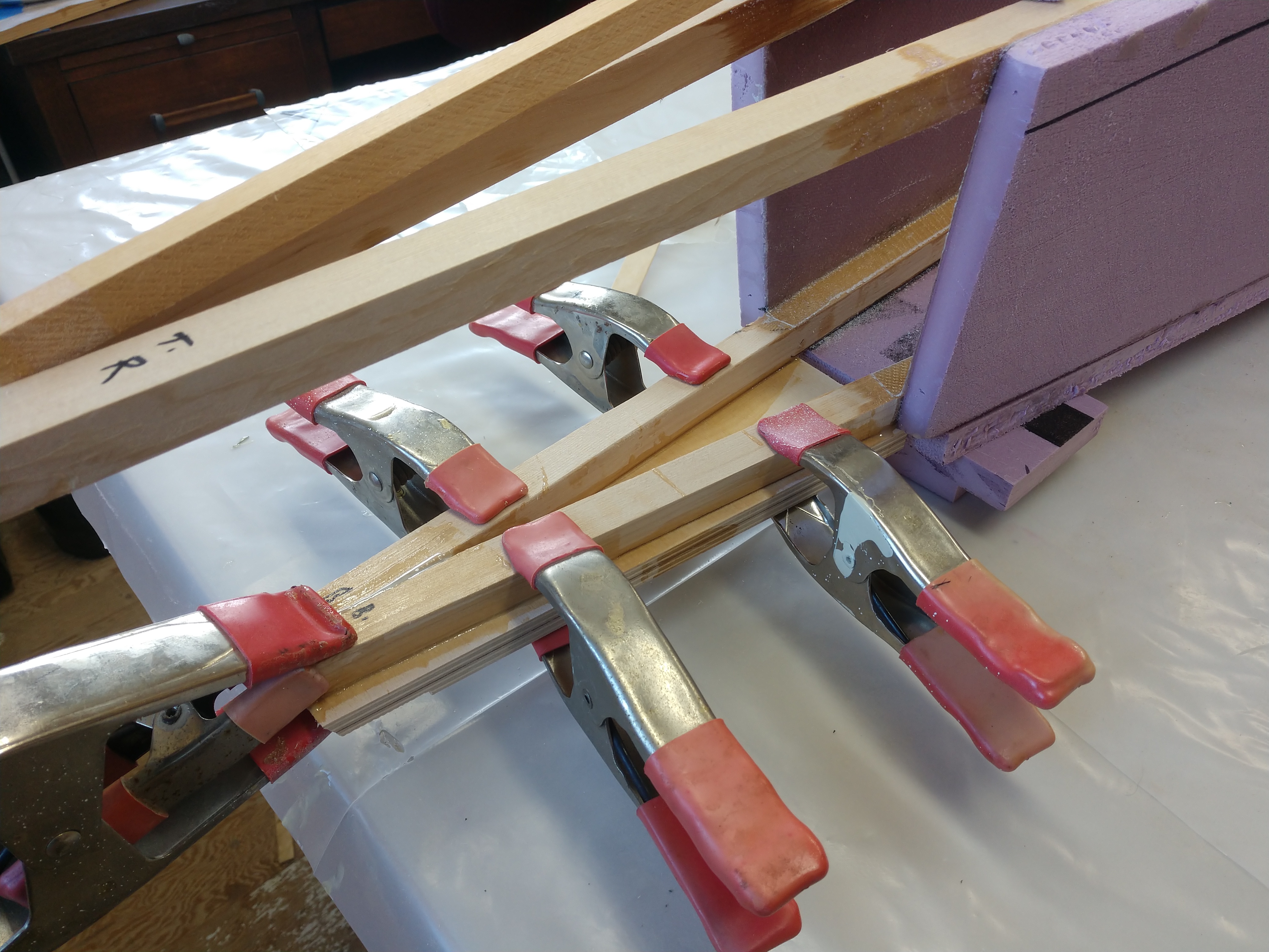
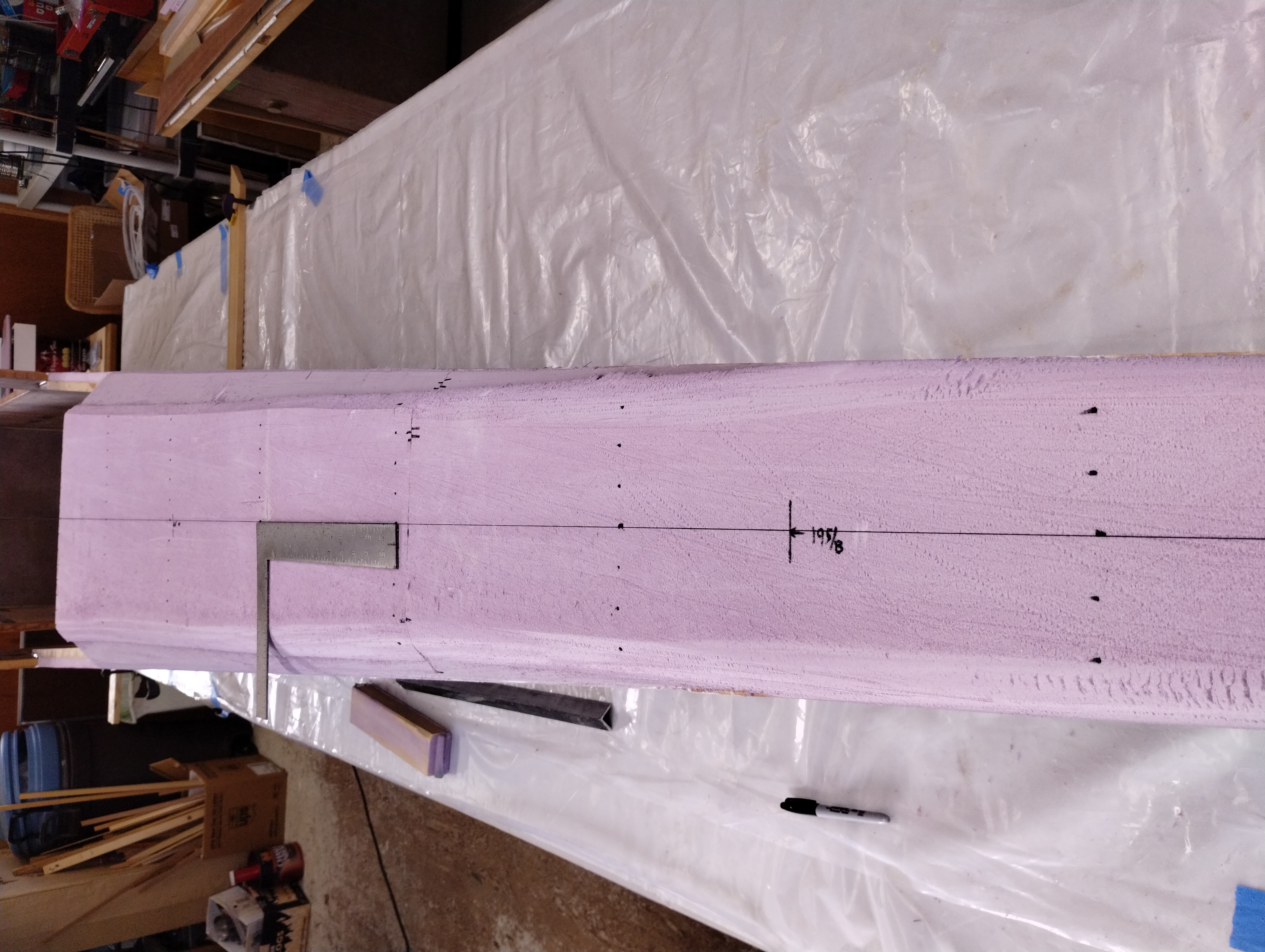
Top view of the same location. Several details to call out here;
* Shims are inserted to replicate the final spacing between the upper longeron
tails. The lower longerons need to be tapered in width to meet the 3/4"-to- 1/2"
final dimension. Marking the length of the taper is other purpose of this layout
exercise.
* All these parts are in their "square cut" status
* Overlaying a 1/2" strip of spruce on the front of the tail plate
allows marking it with bevel lines for final fitting the longerons and the
bottom edge
* After the tail plate bevel is cut, the spring plate can slide into position
for marking its final bevel cut
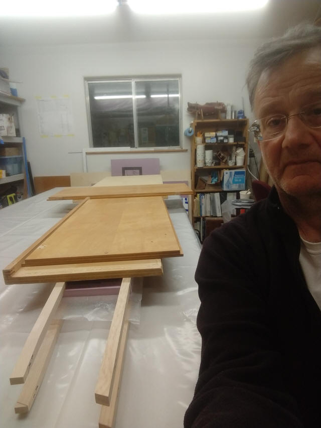
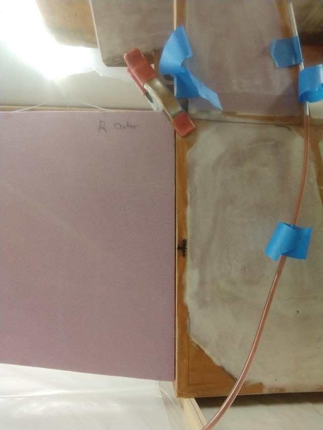
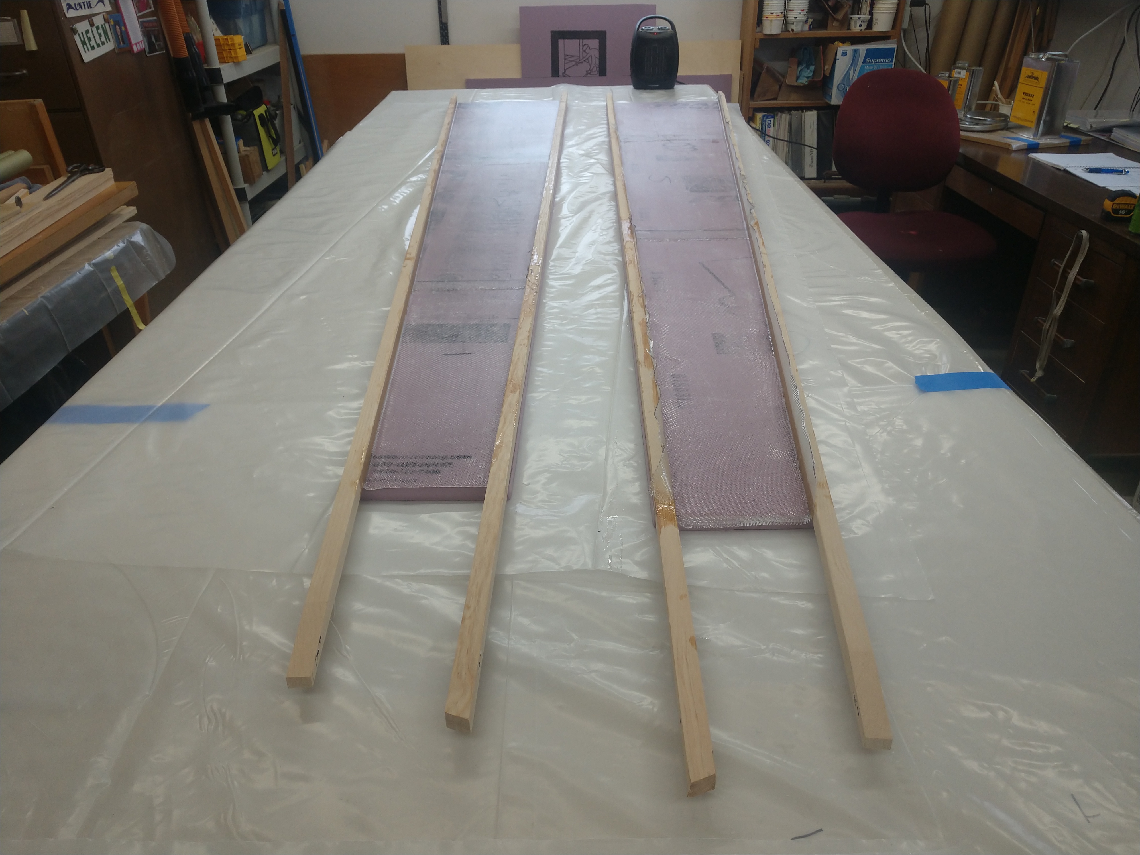
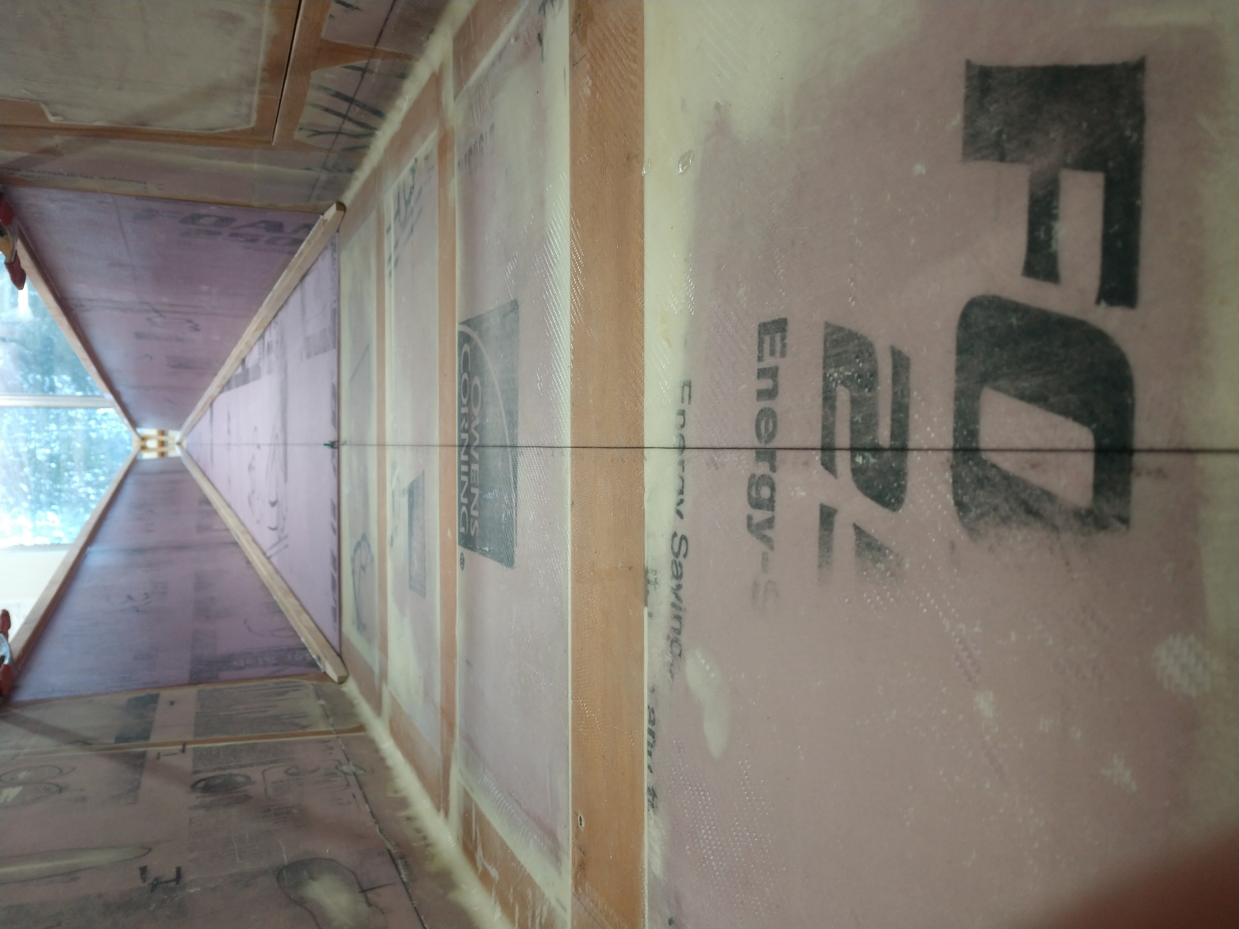
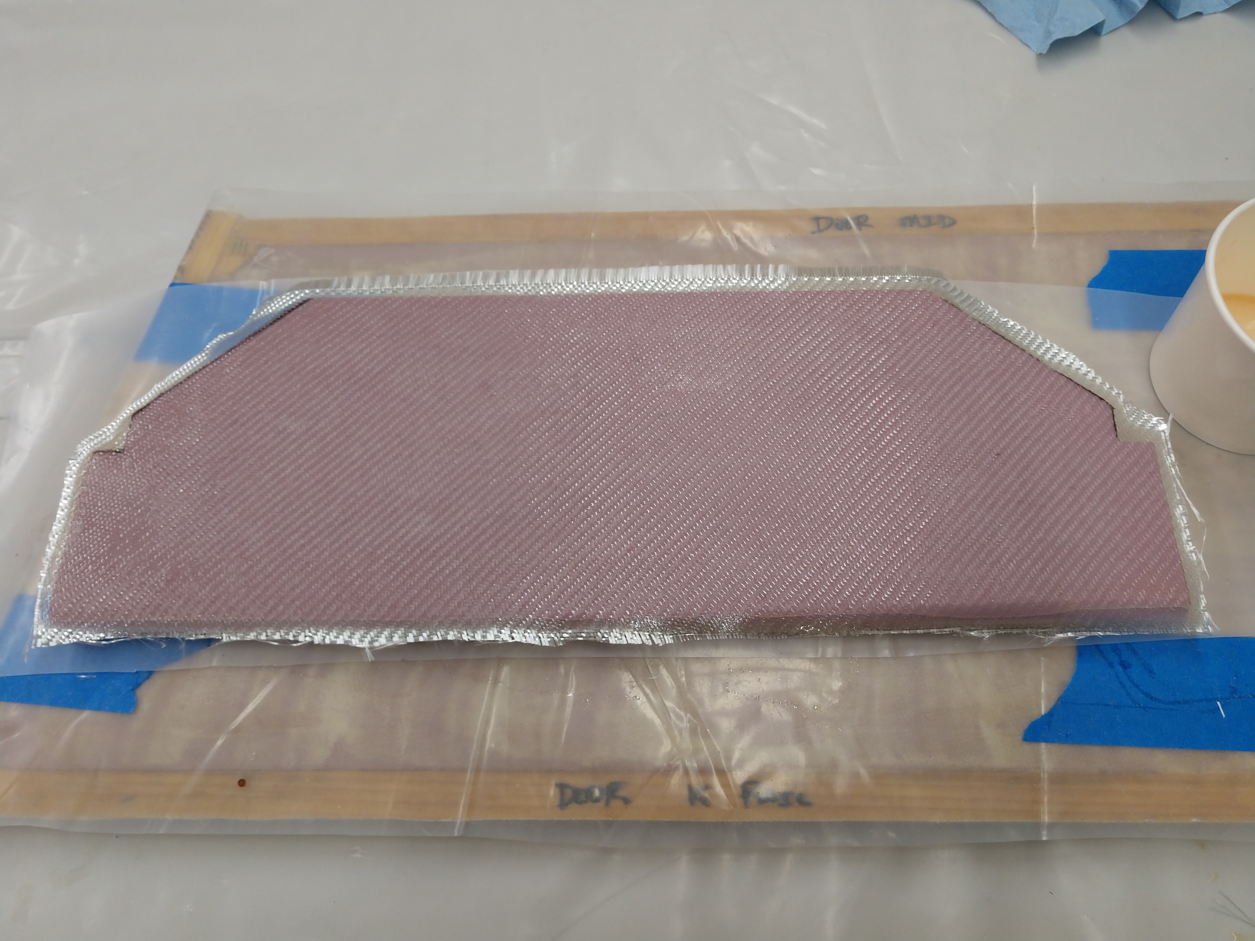
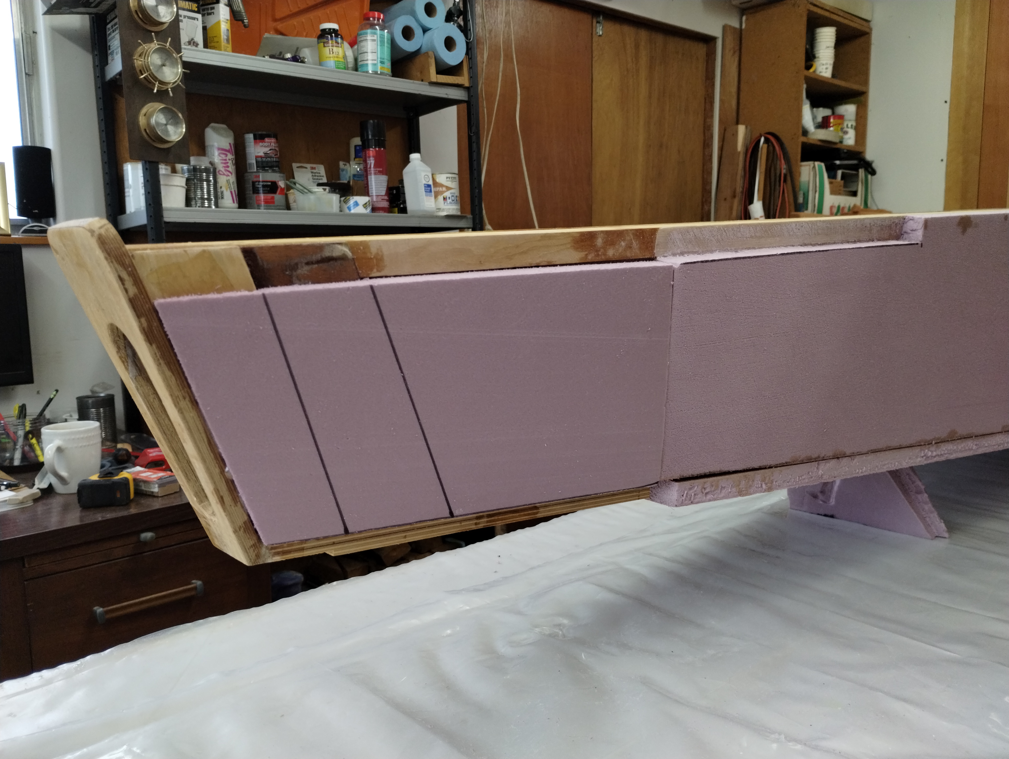
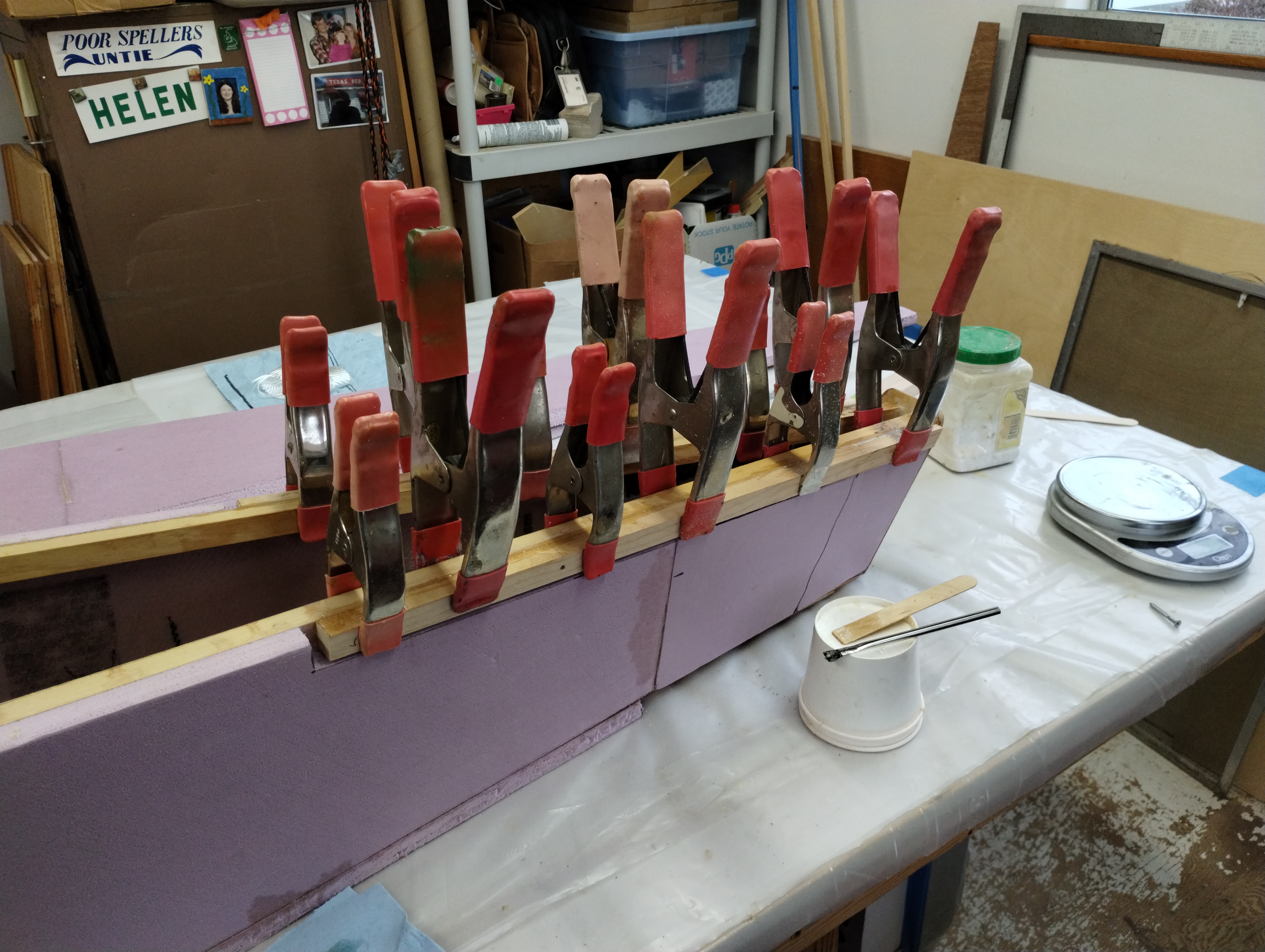
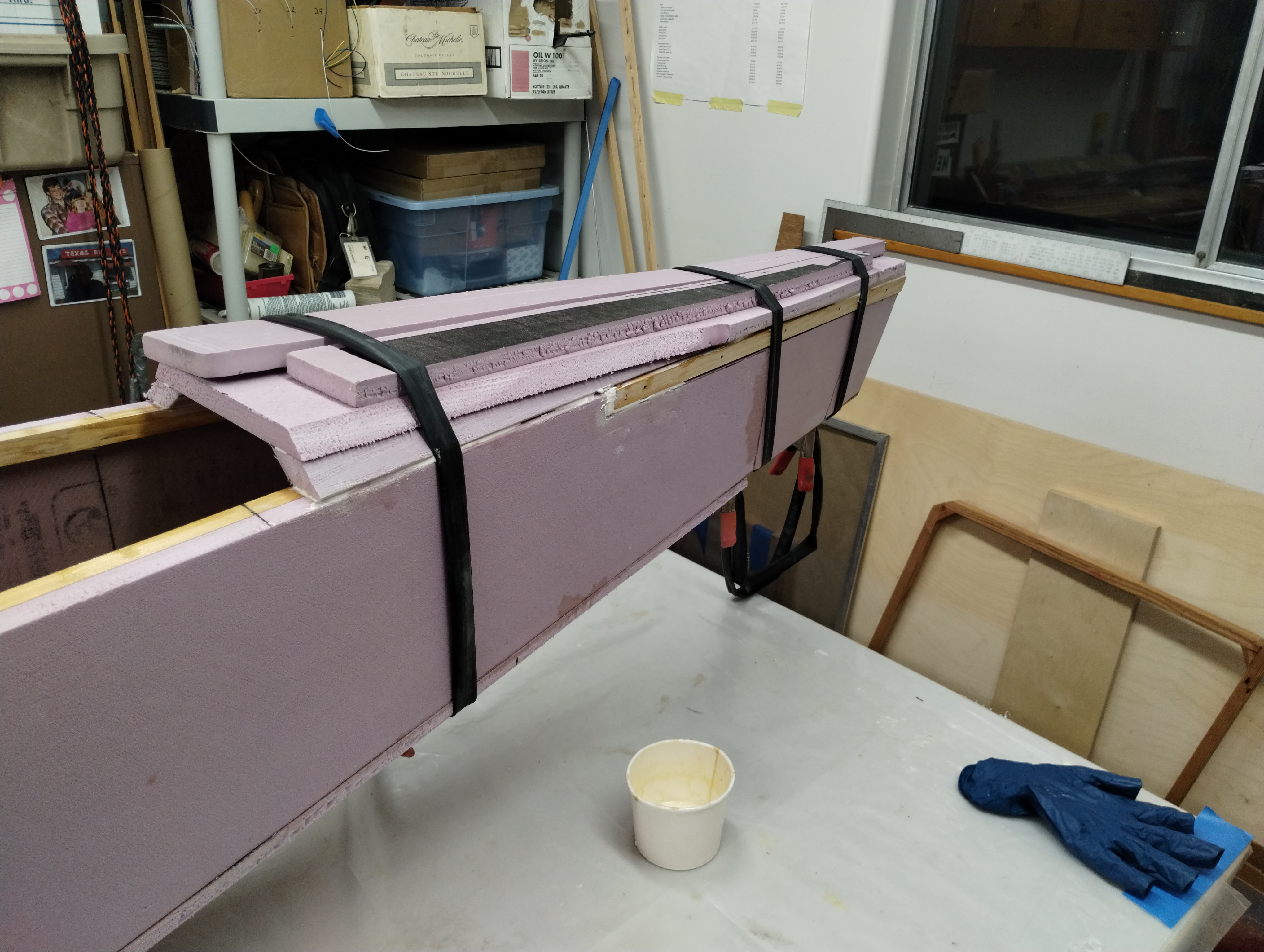
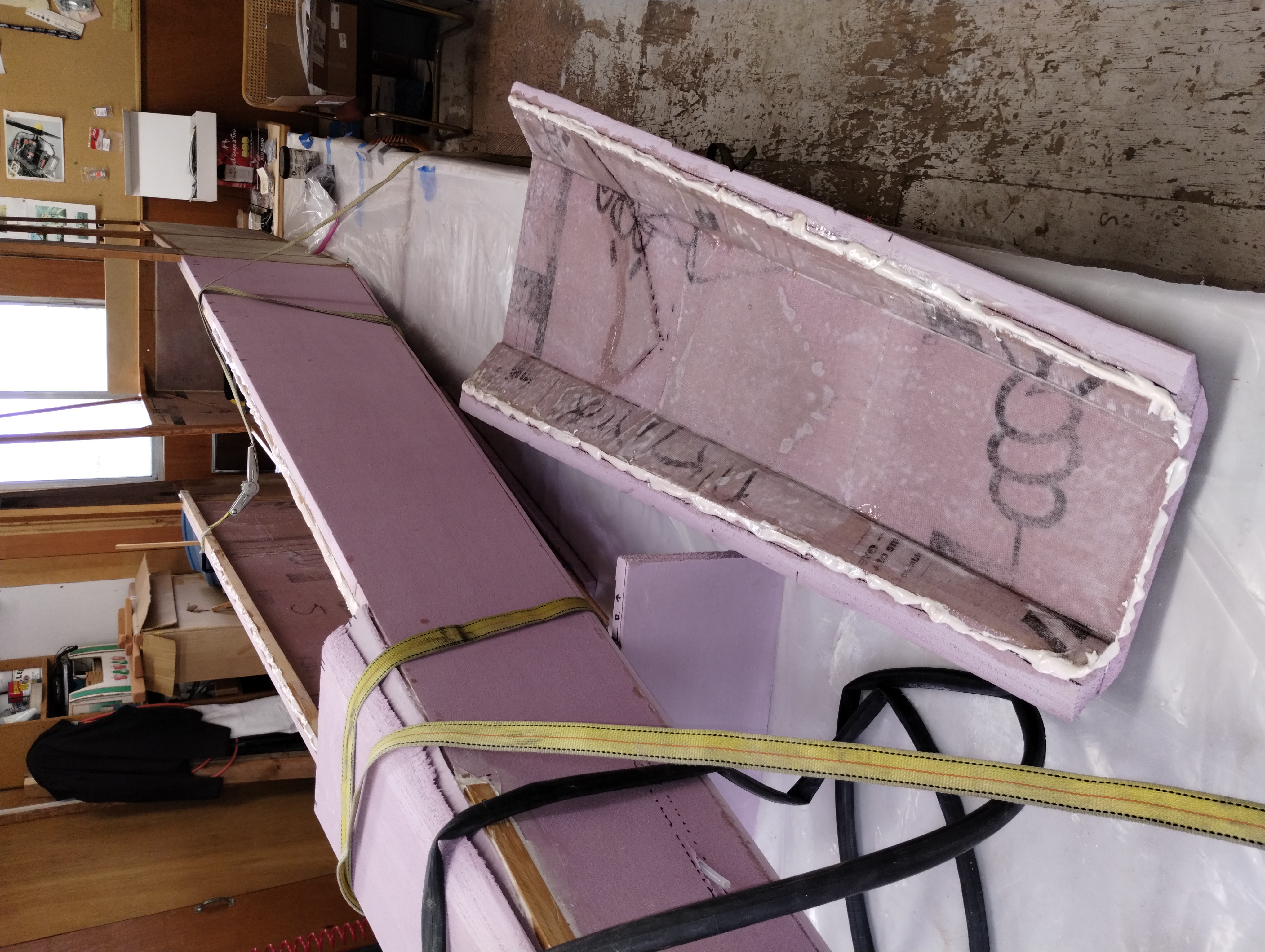
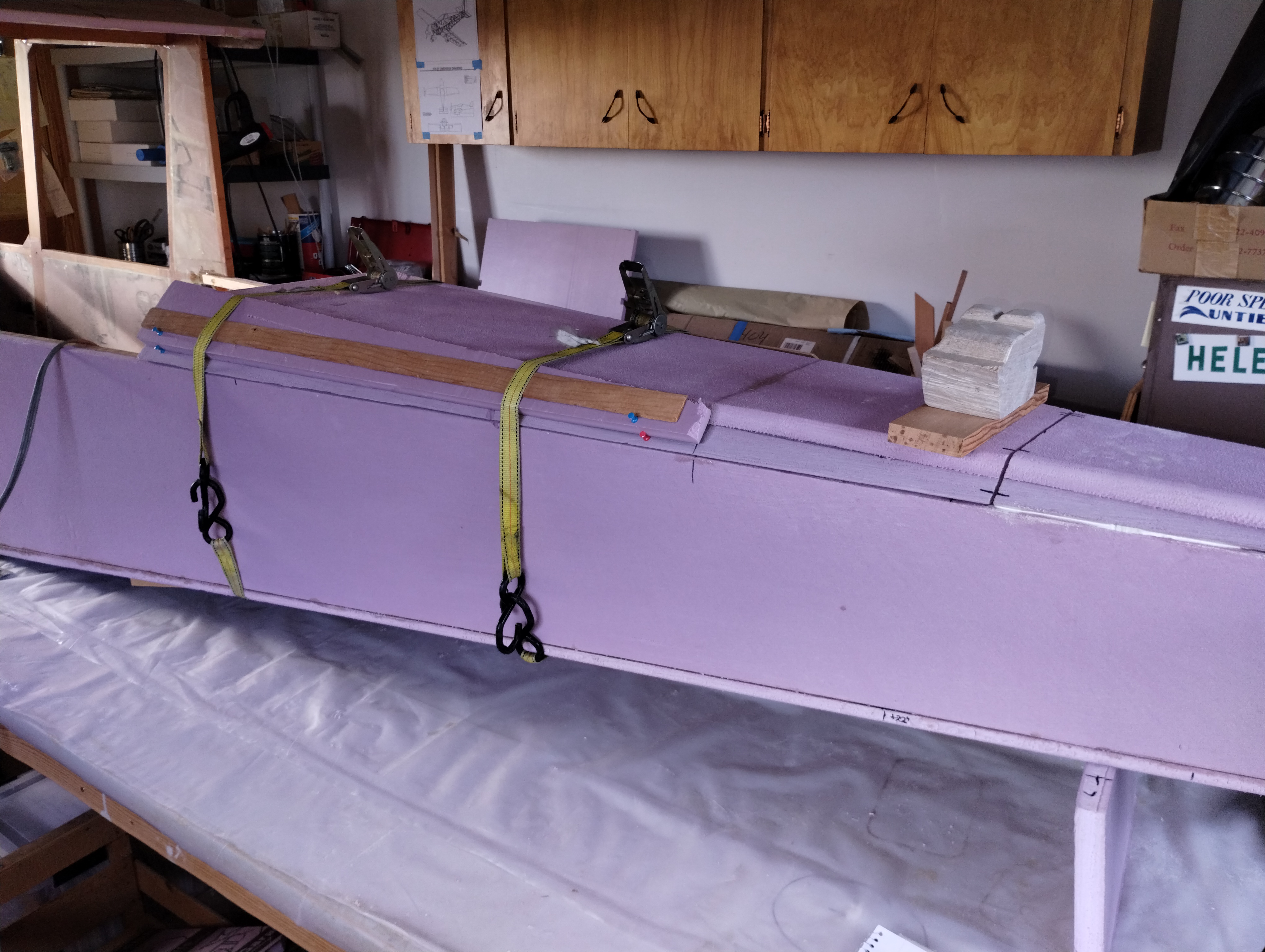
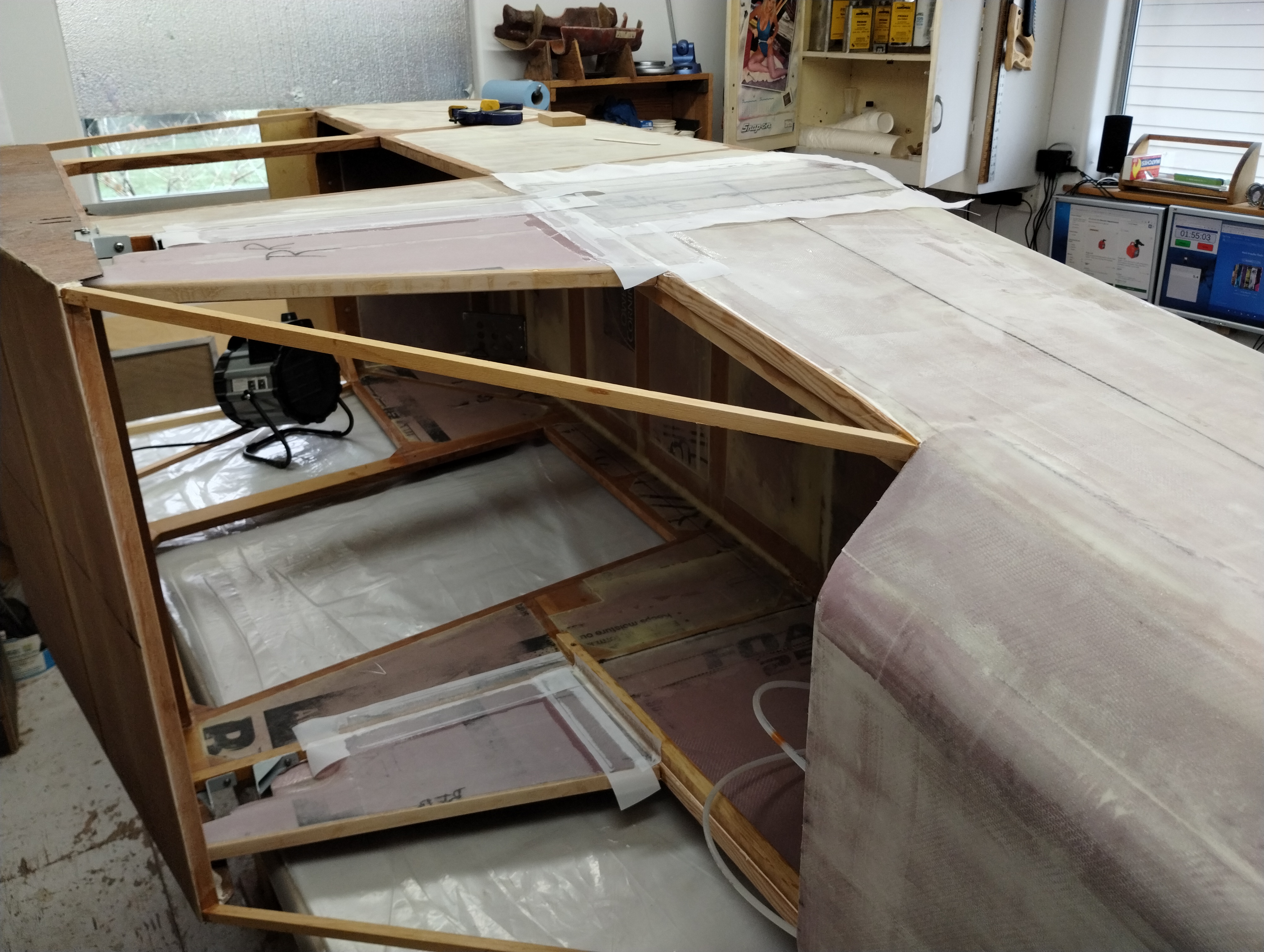
I laid out the longerons on an XPS sheet,
measured and marked the positions and sliced it up. These photos show the panels
with the longerons laying on them and then later that evening glued up and using
plywood boards to weight/ clamp the resin into solid contact. I'll add the
remaining panel sections after I fine-tune the longeron tails into place on the
spring and tail plates.
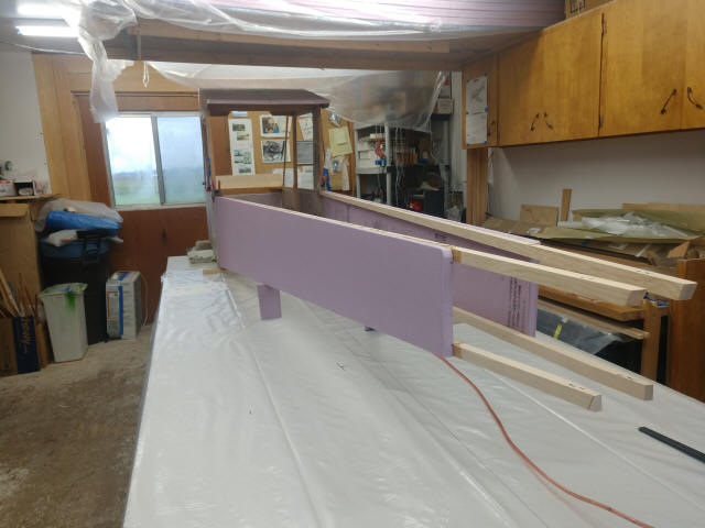
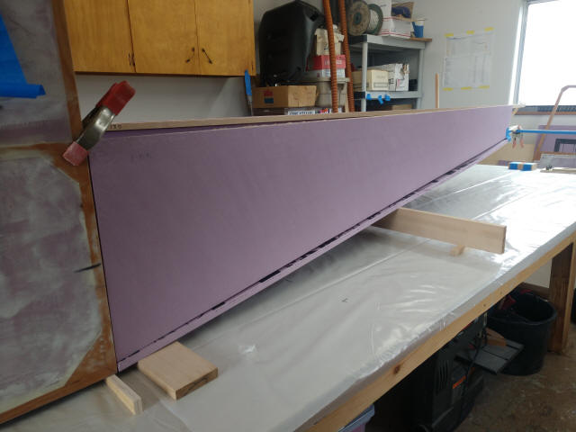
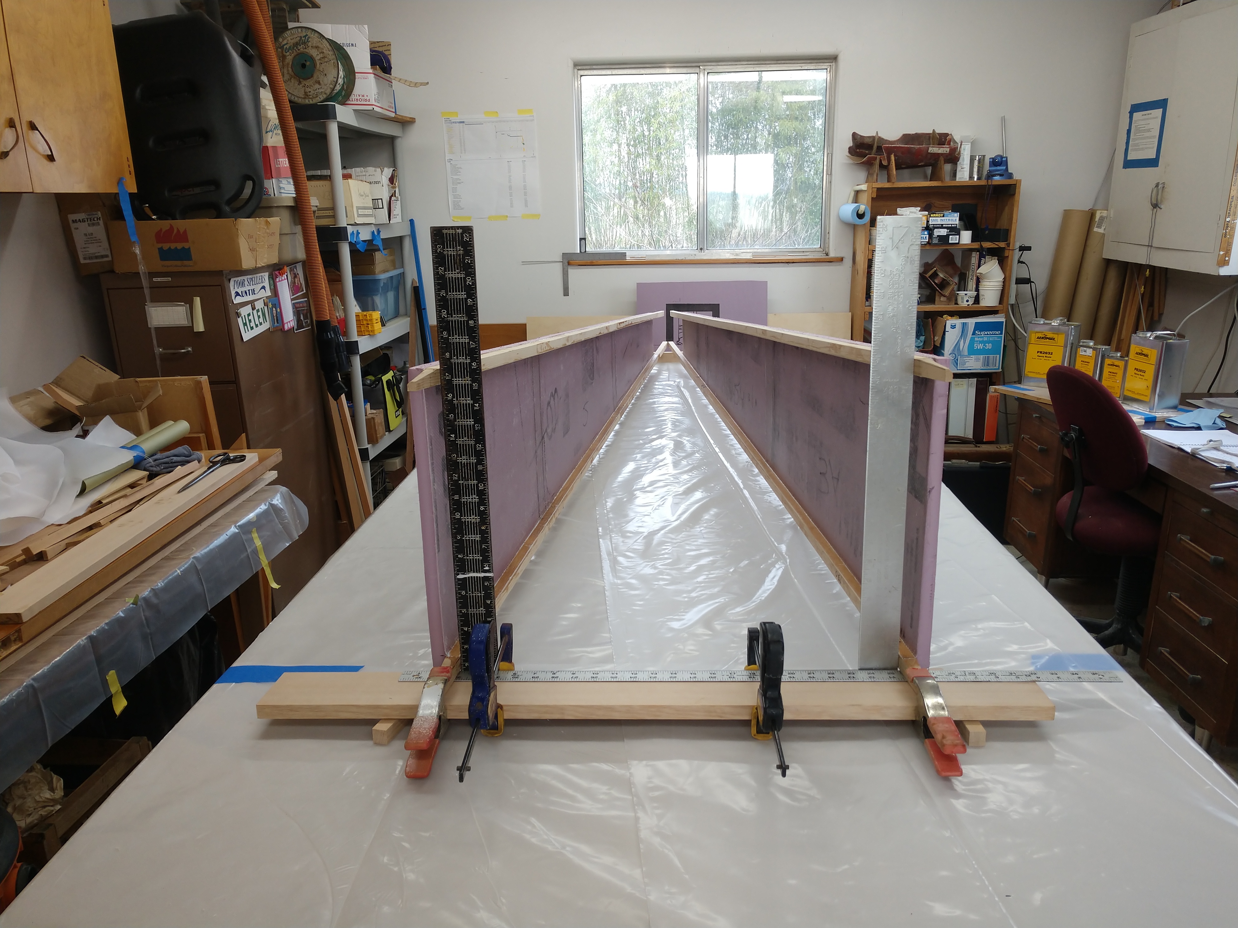
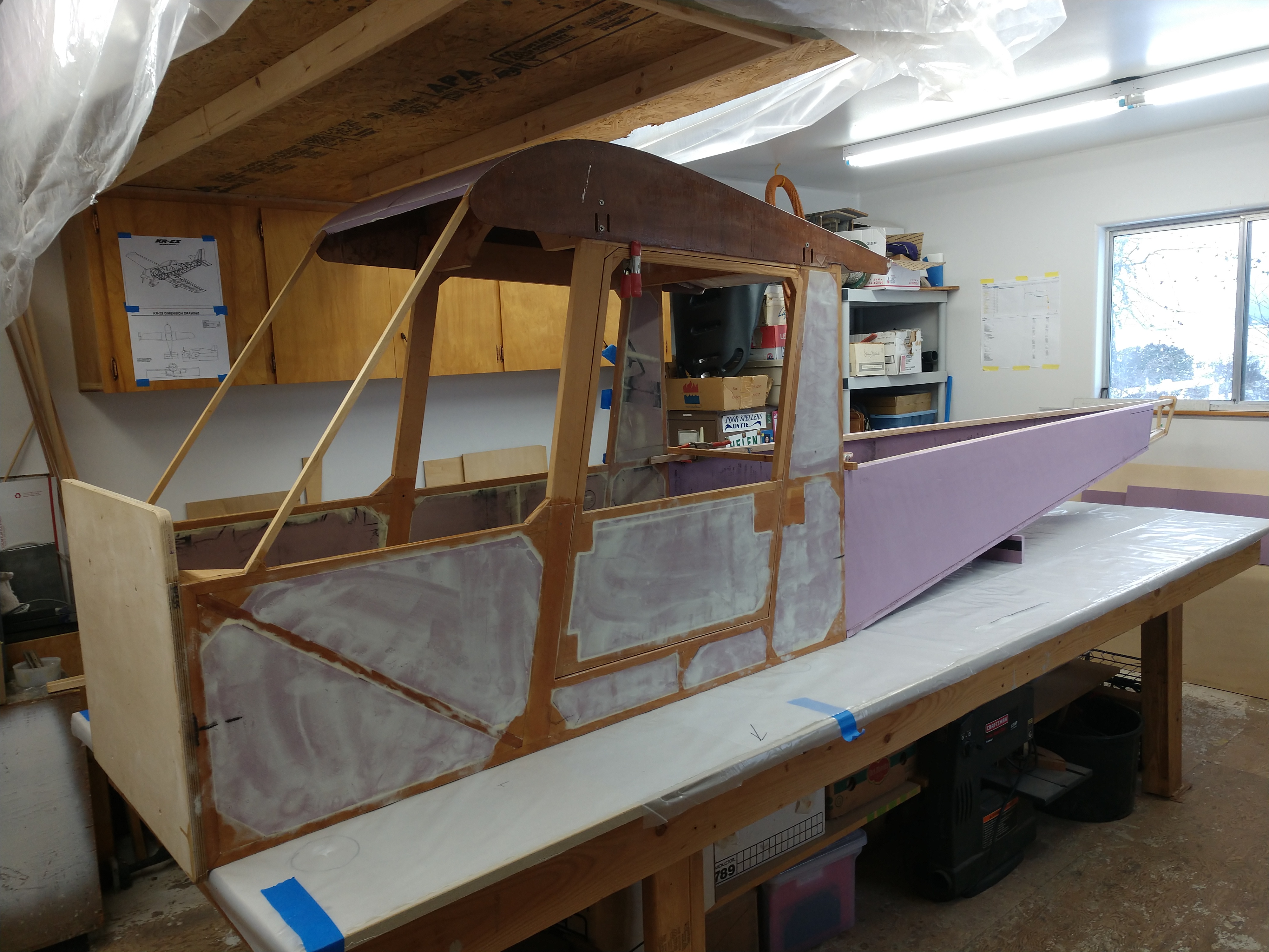
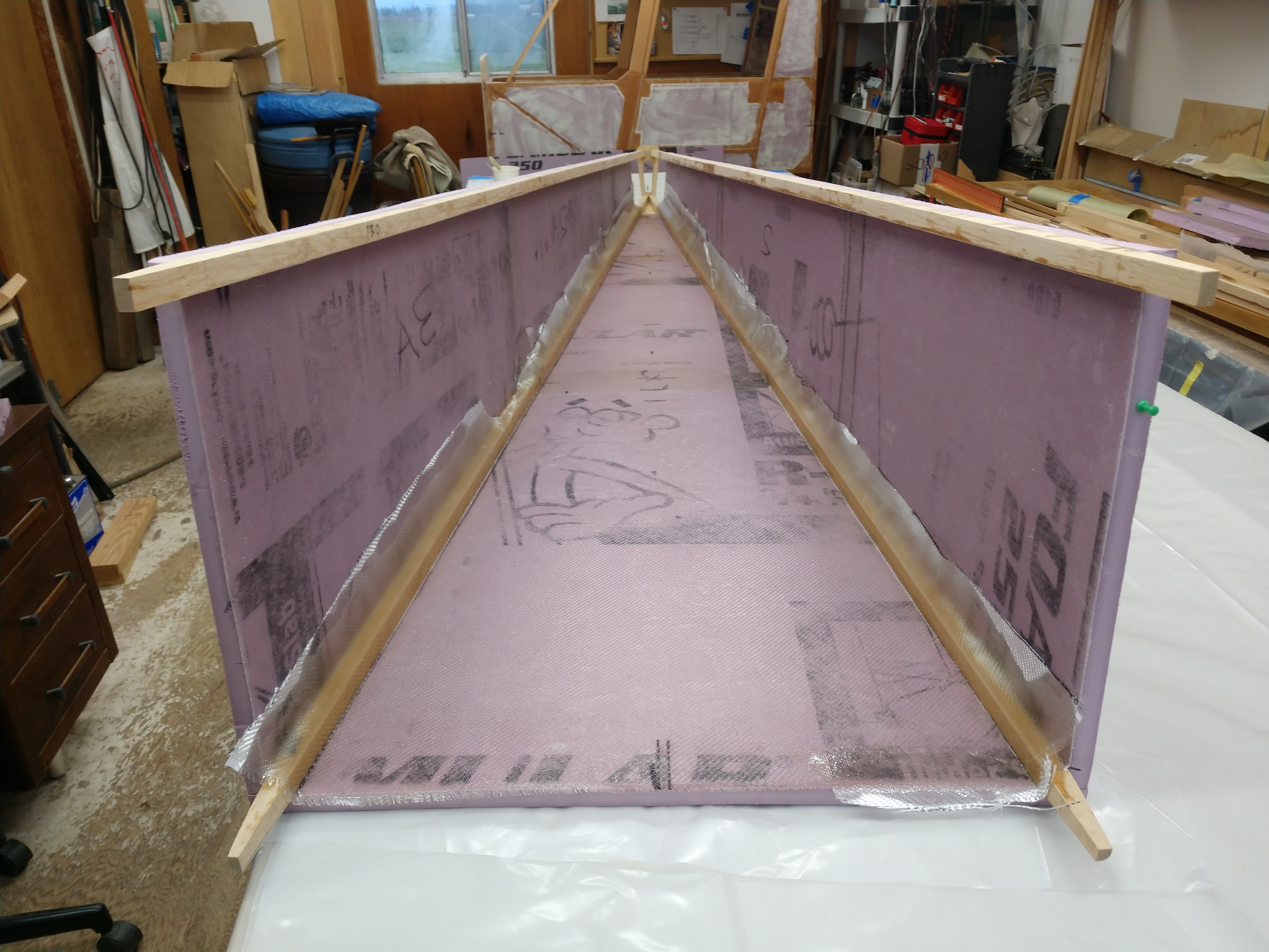
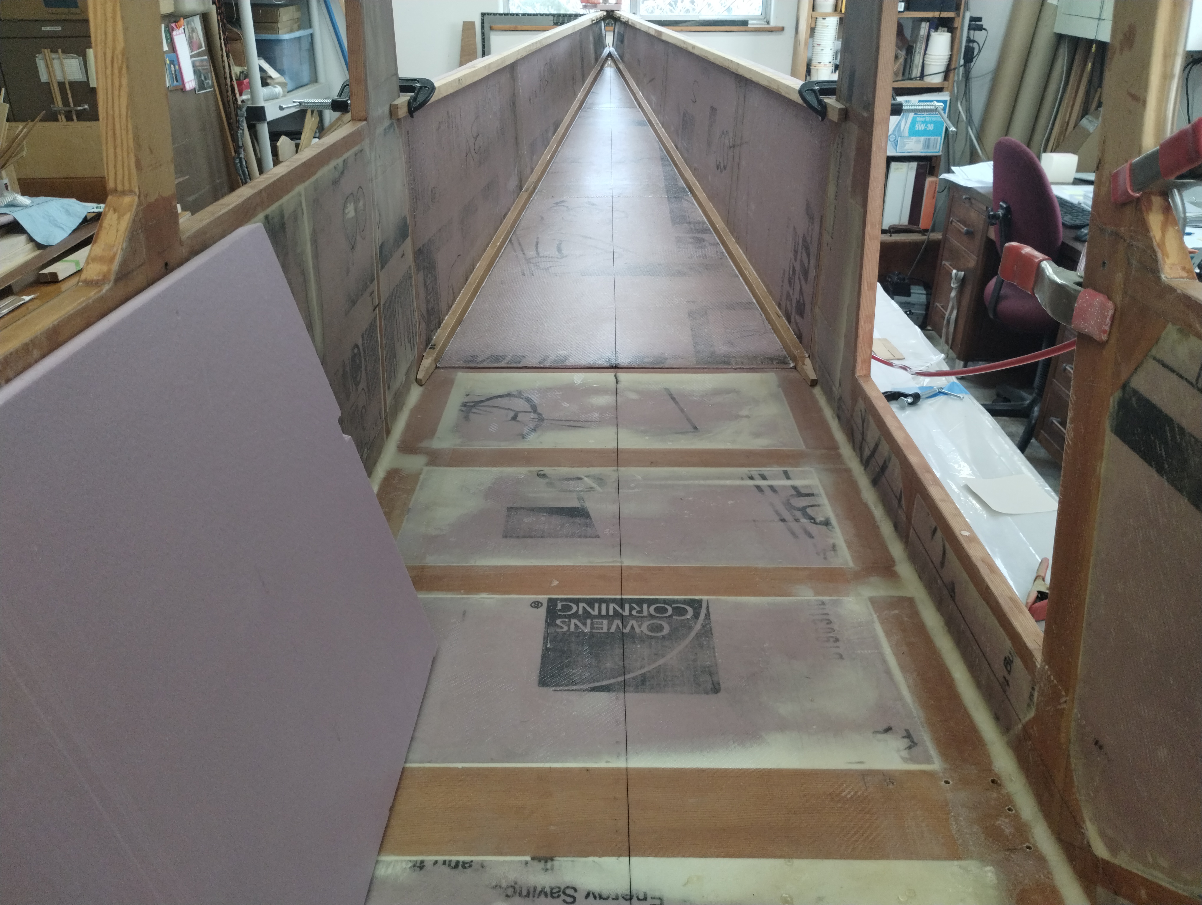
After the sides epoxy cured, stand them up and confirm proper seam gap at the
cabin wall for equal reveal on both sides when the tails are in the position
jig. So far so good.
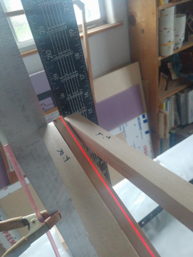
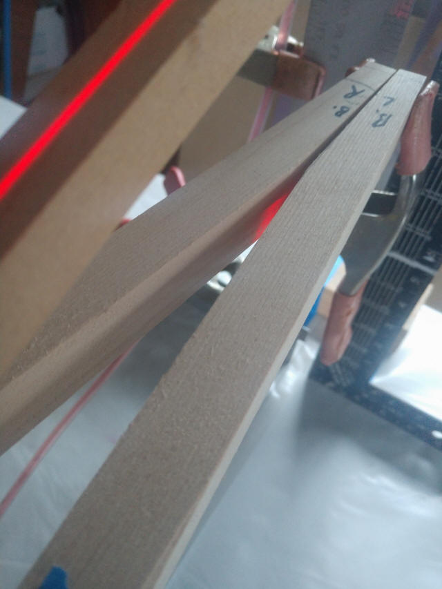
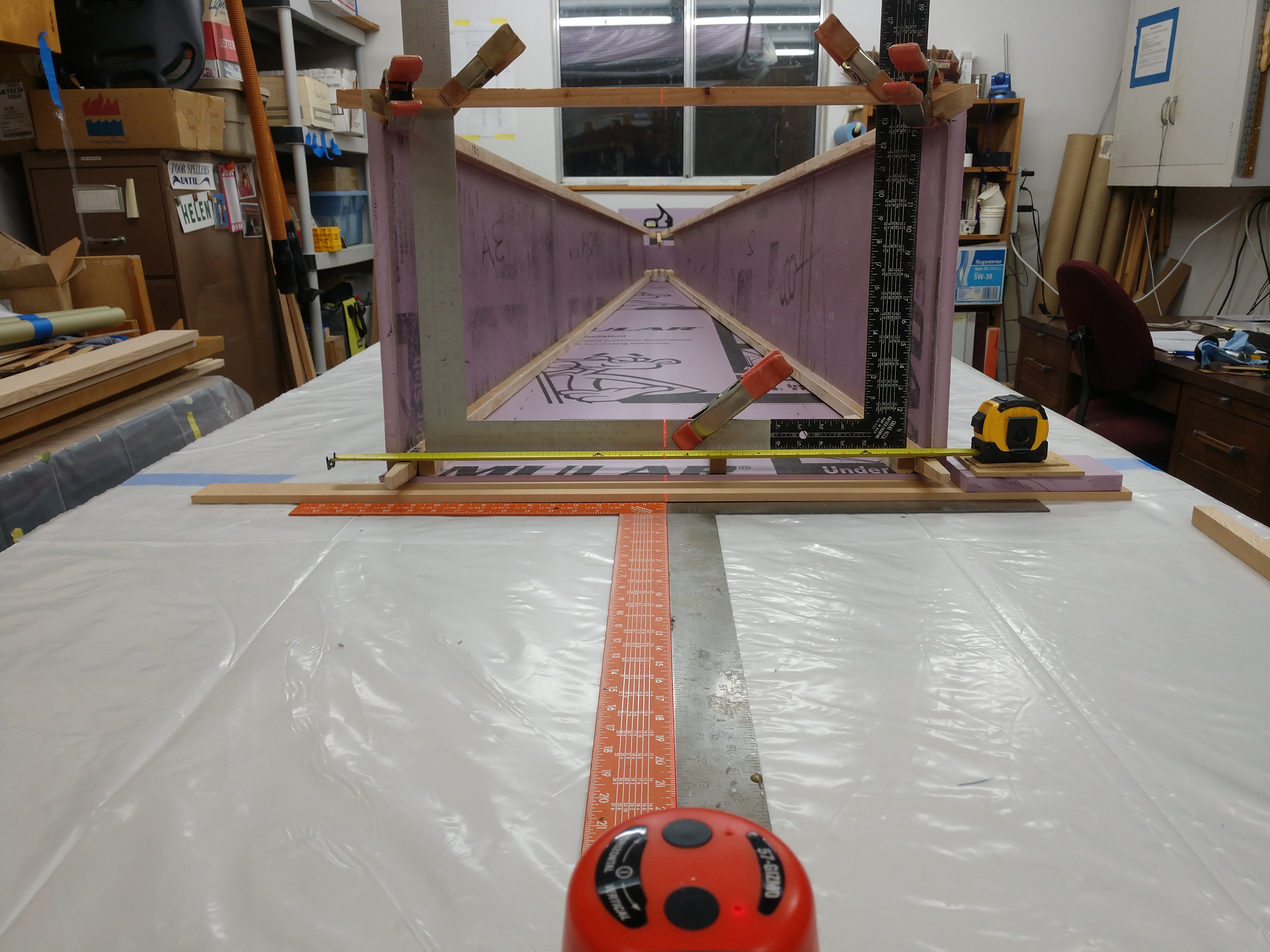
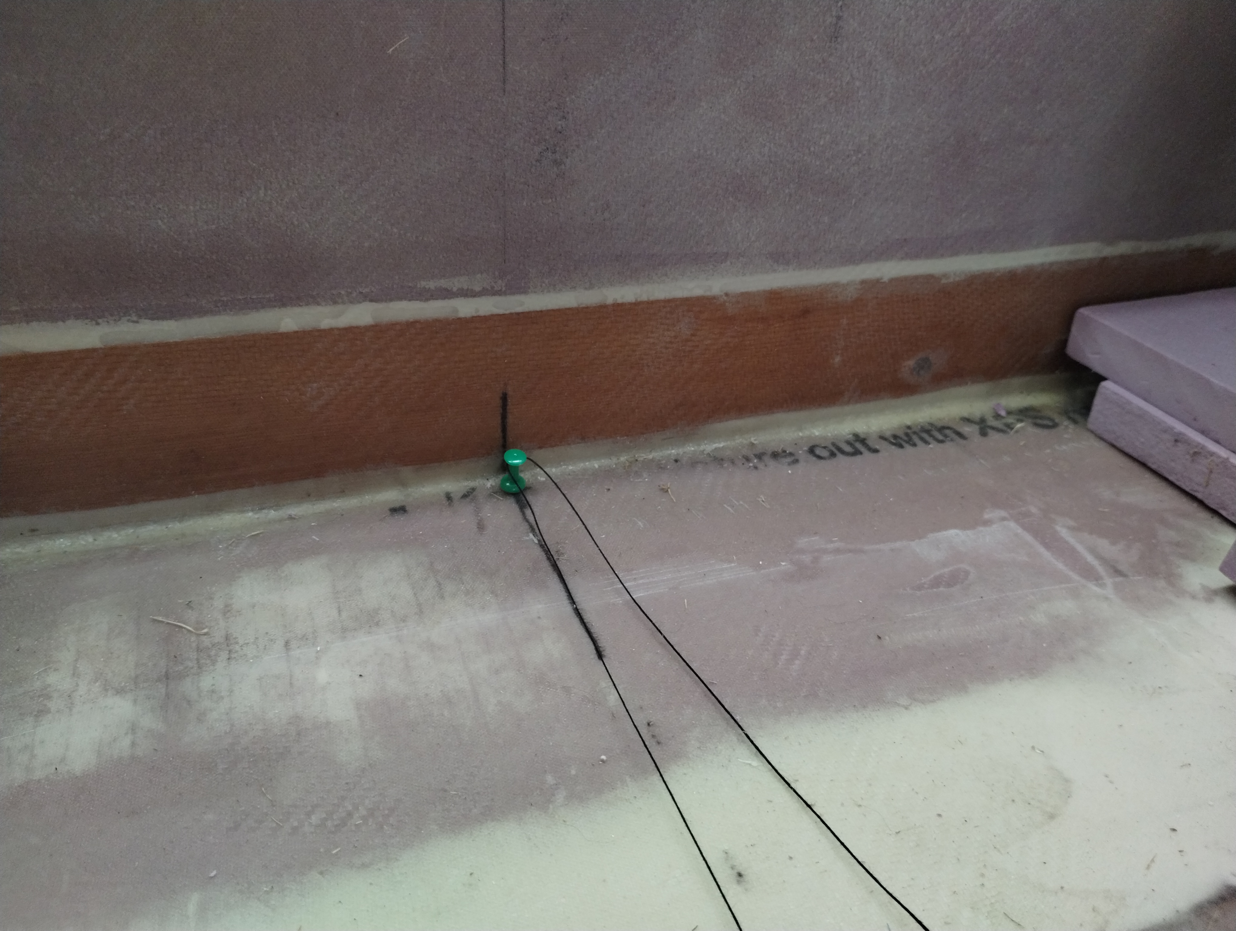
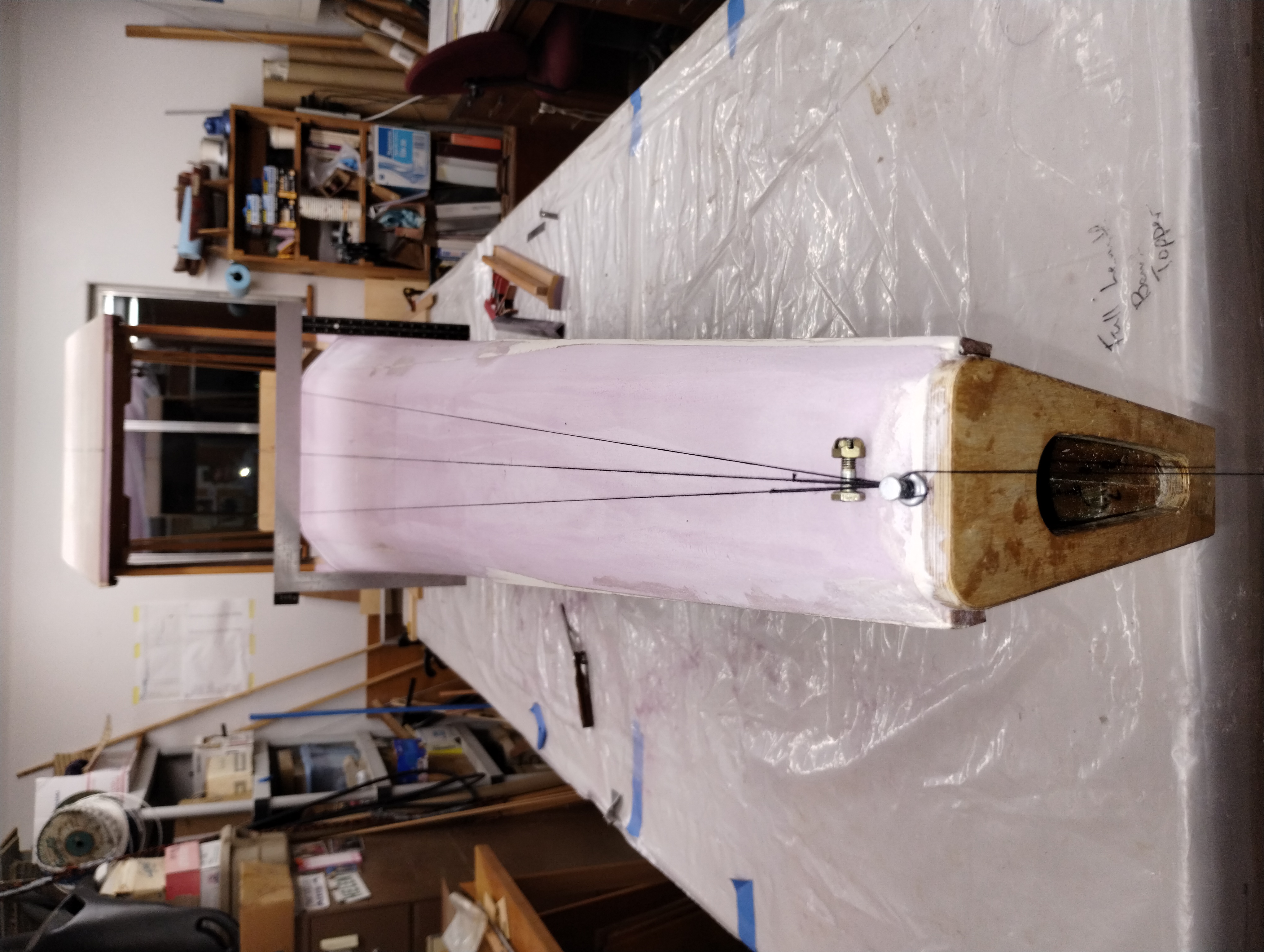
I borrowed neighbour's [Dr. Ken Melvin, M.D., PhD and a whole bunch of other
degrees I don't even understand...] laser level to shoot a straight vertical
line through the cabin center to the tail. It's [very] slightly out of true but
I think I can work that back when I glue the bottom skin on. The top tails
center on a 1/2" spacer and you can see how close it is in the upper photo. The
lower photo shows the laser beam is centered between the lower tails so that's
good.
The bottom skin was cut slightly "too wide" allowing me to perfect the
alignment when it gets glued to the side panels.
Now it's on to glassing the interiors of both side panels before joining the bottom skin and locking the structure into alignment...
Since the longeron tails were all trued up to the tail plate time to get it glued on. I predrilled the plywood and used aircraft nails to clamp the butt joints. The metal yard stick was aligned with the flat tail plate surface and I made diagonal measurements ensuring it was parallel and centered to the forward end of the empennage.
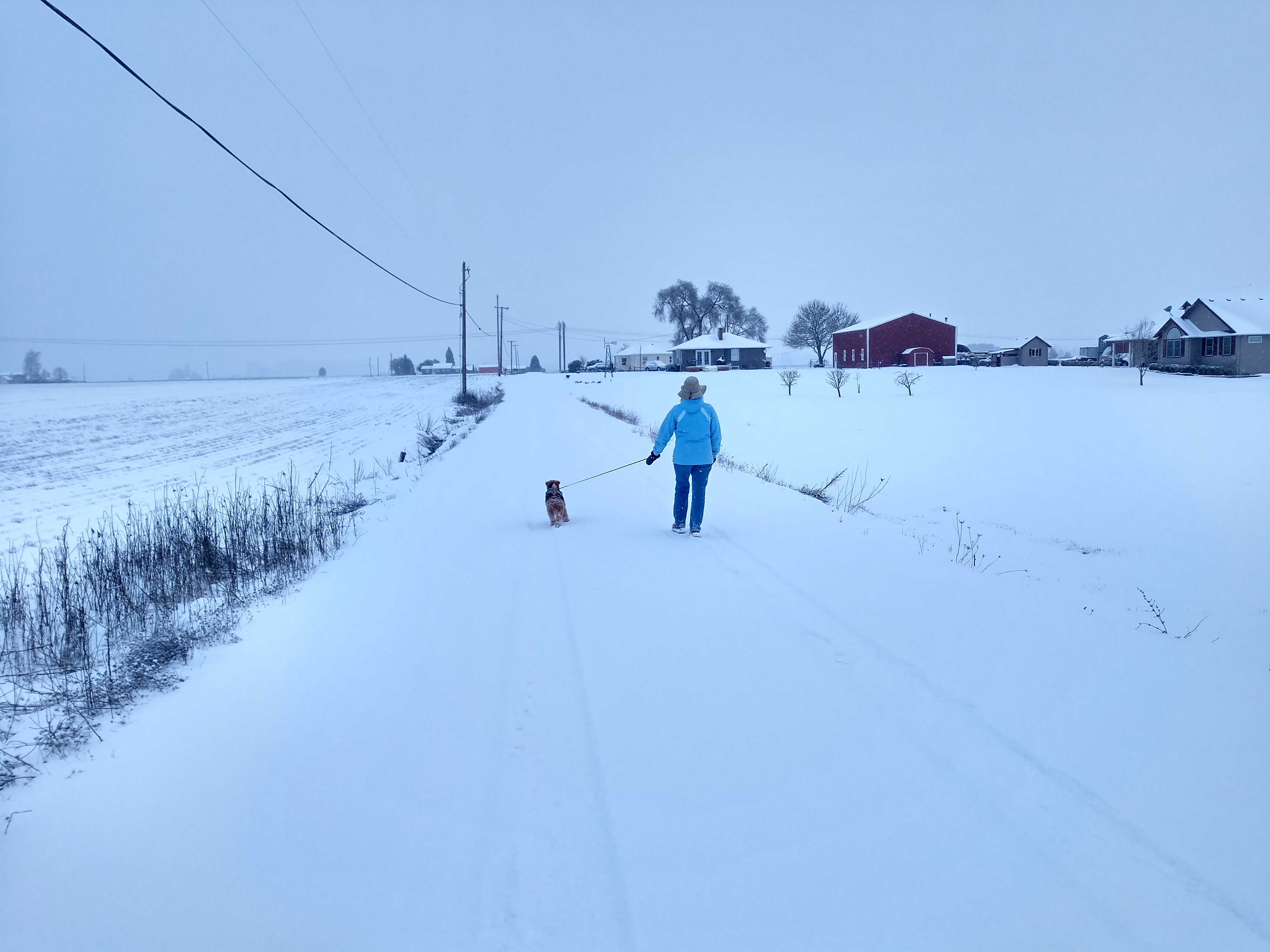
And then it snowed...
I had to get an idea what it will look like later. And the string line showed
the alignment is correct to 1/16"; close enough for me.
Glassing the bottom interior skin up onto the longerons.
This is intended as a empennage deck lid bulkhead.
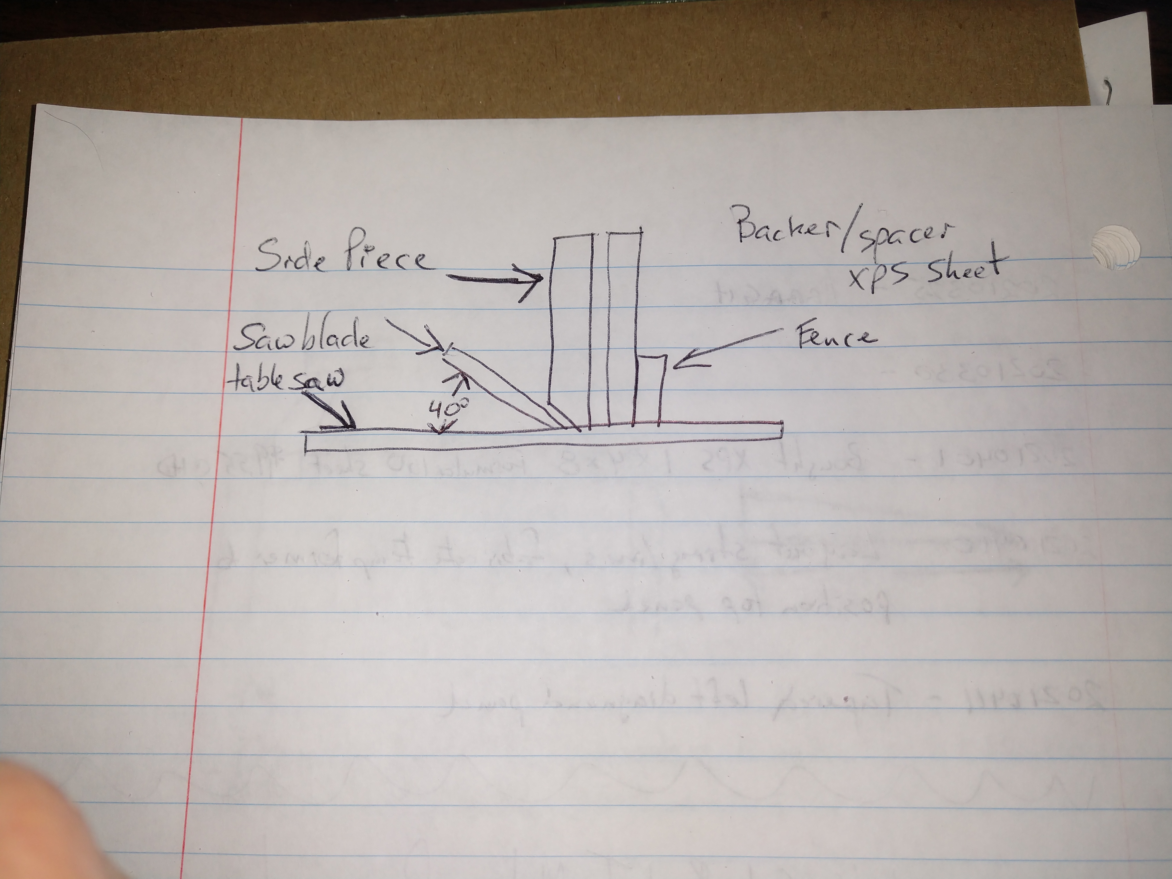
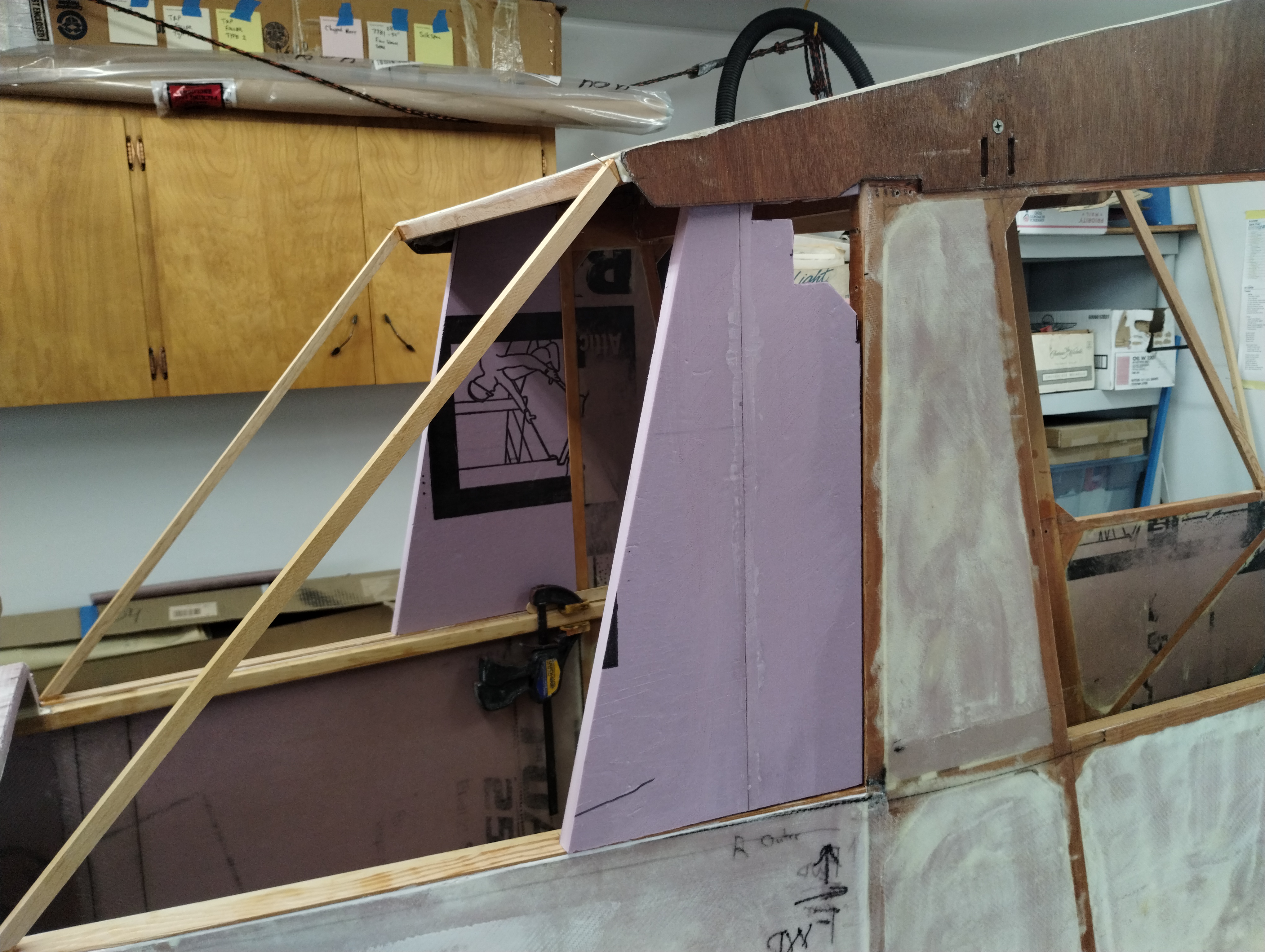
Then I struggled mightily trying to figure out how to build the empennage
deck lid. I couldn't figure out how to cut the bevels on the side profile XPS
pieces. Finally I decided to just try something. I bought a sheet of 1" XPS foam
at the hardware store to give me more material to work with in setting the
bevels.
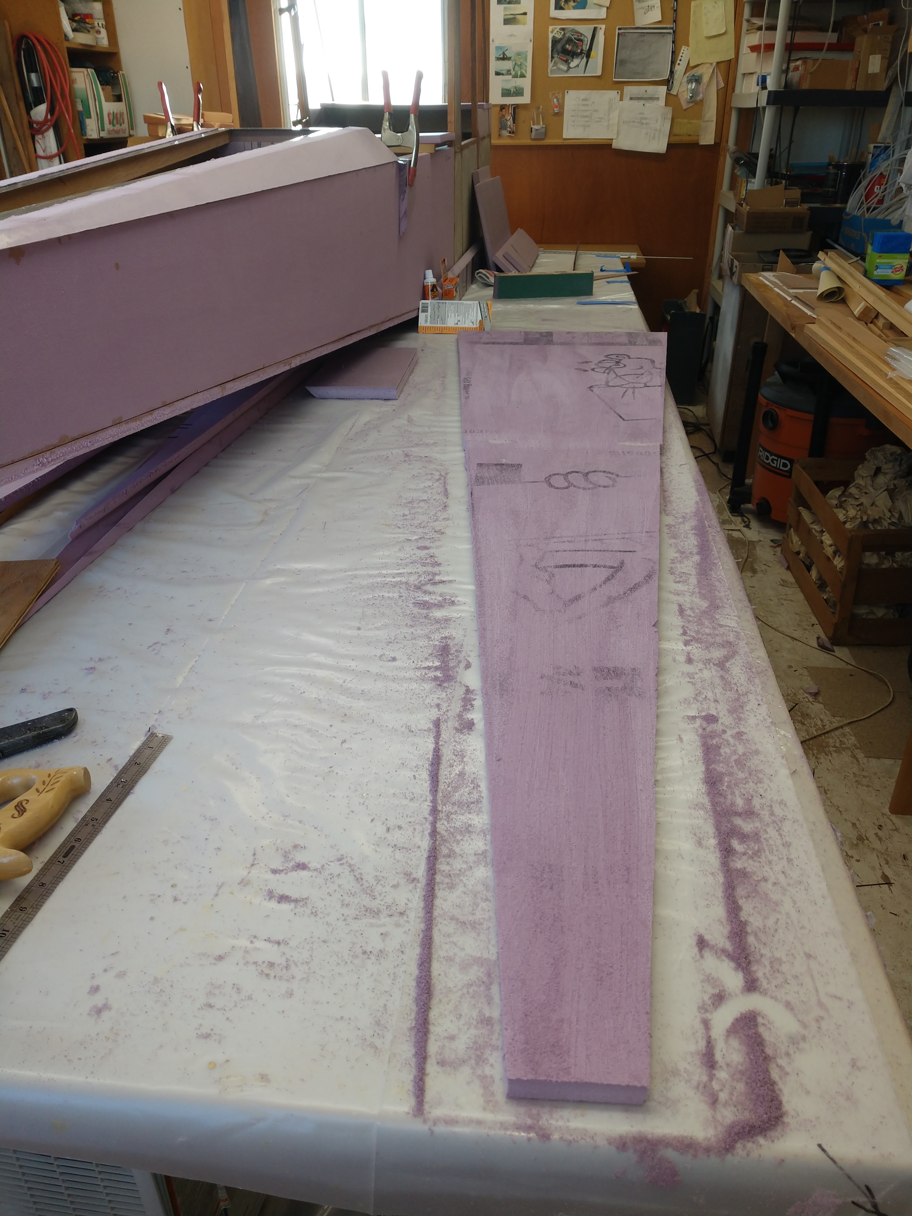
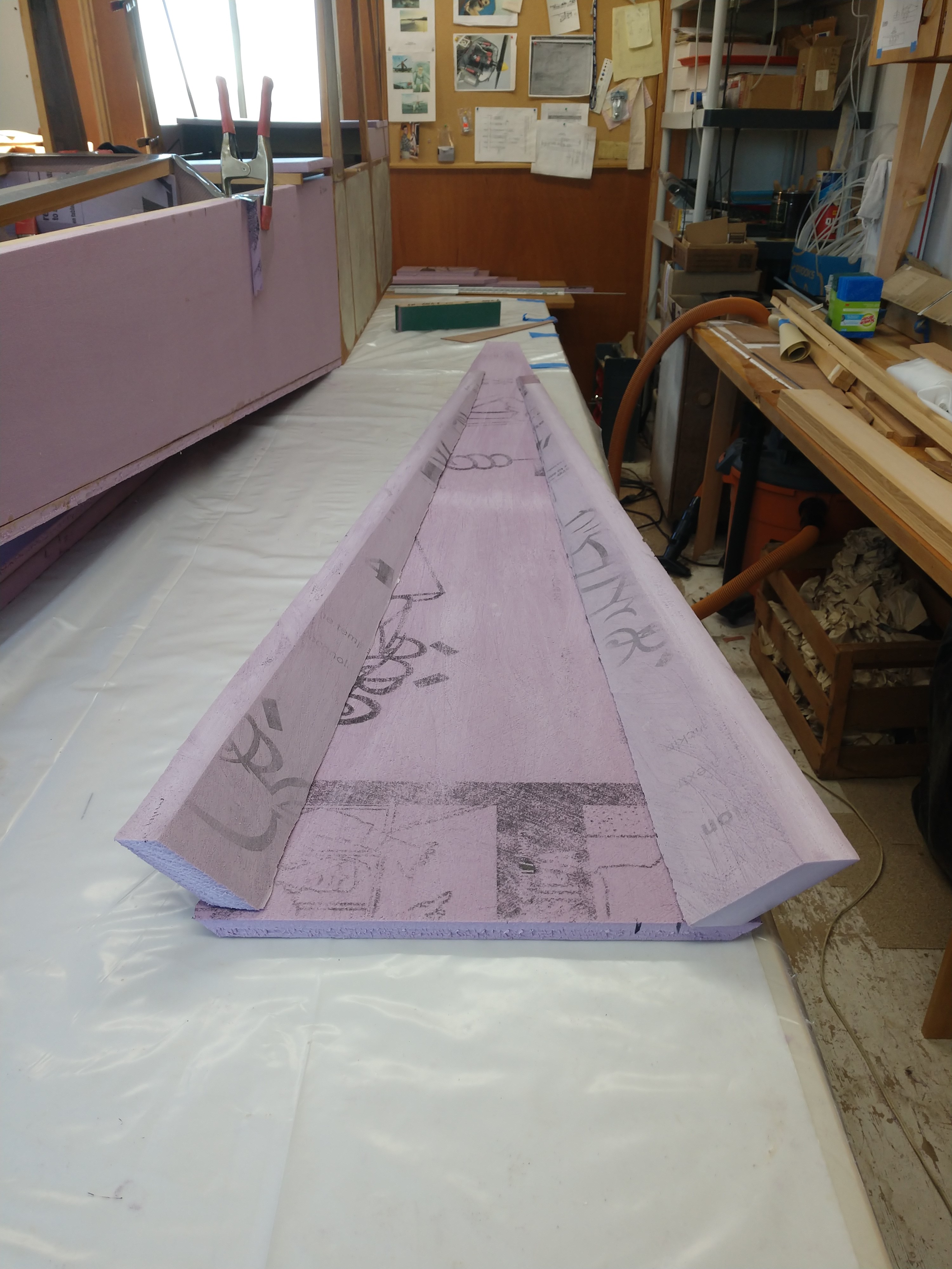
You can see the resulting profile pieces resting on top of the top longerons.
I rough cut the top and sanded it to help the resin bite into the surface. I'm
putting all the label side of the material on the inside so the exterior will be
uniform to paint. I bonded the profile pieces and hey, it's 3 dimensional!
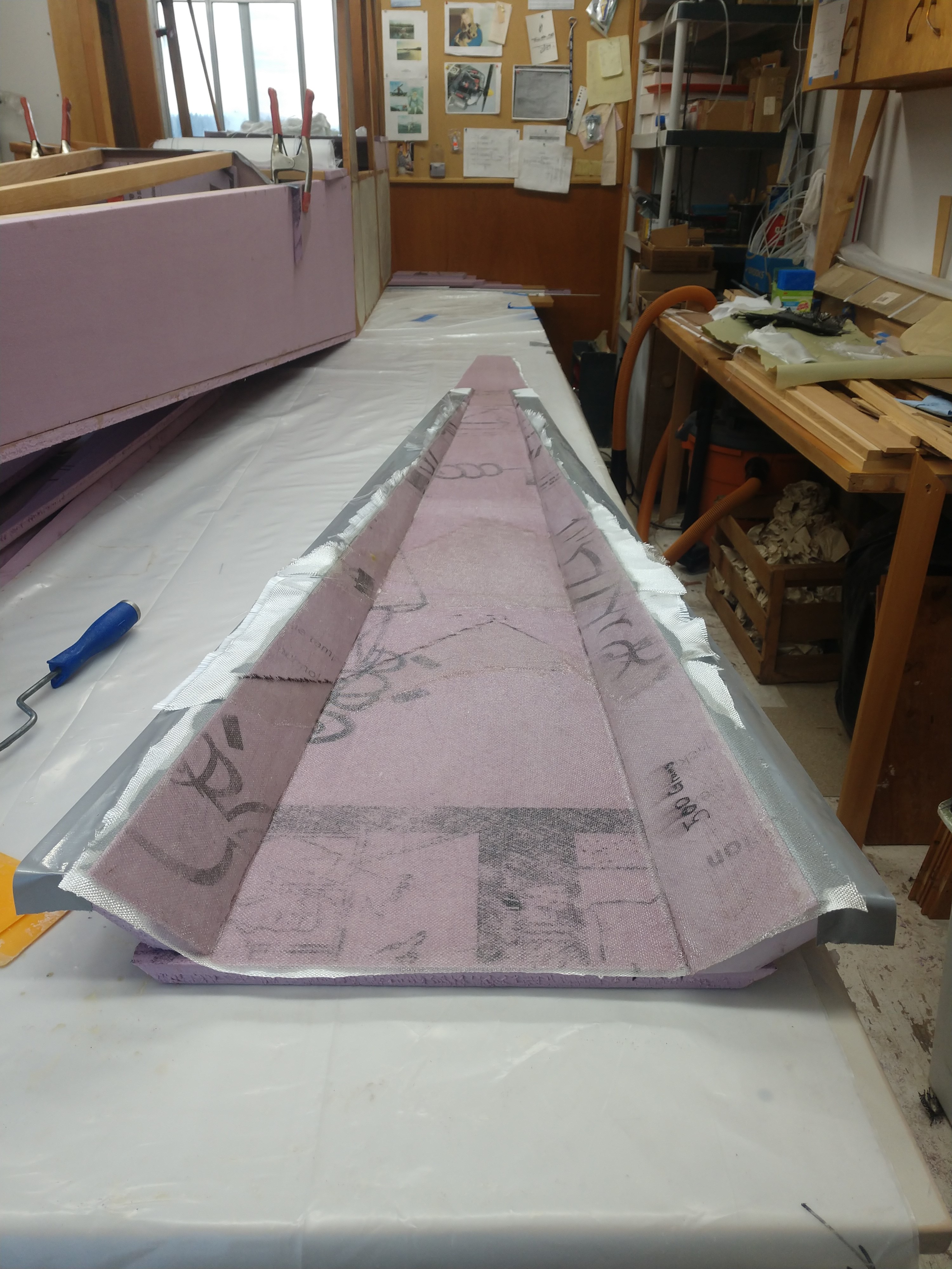
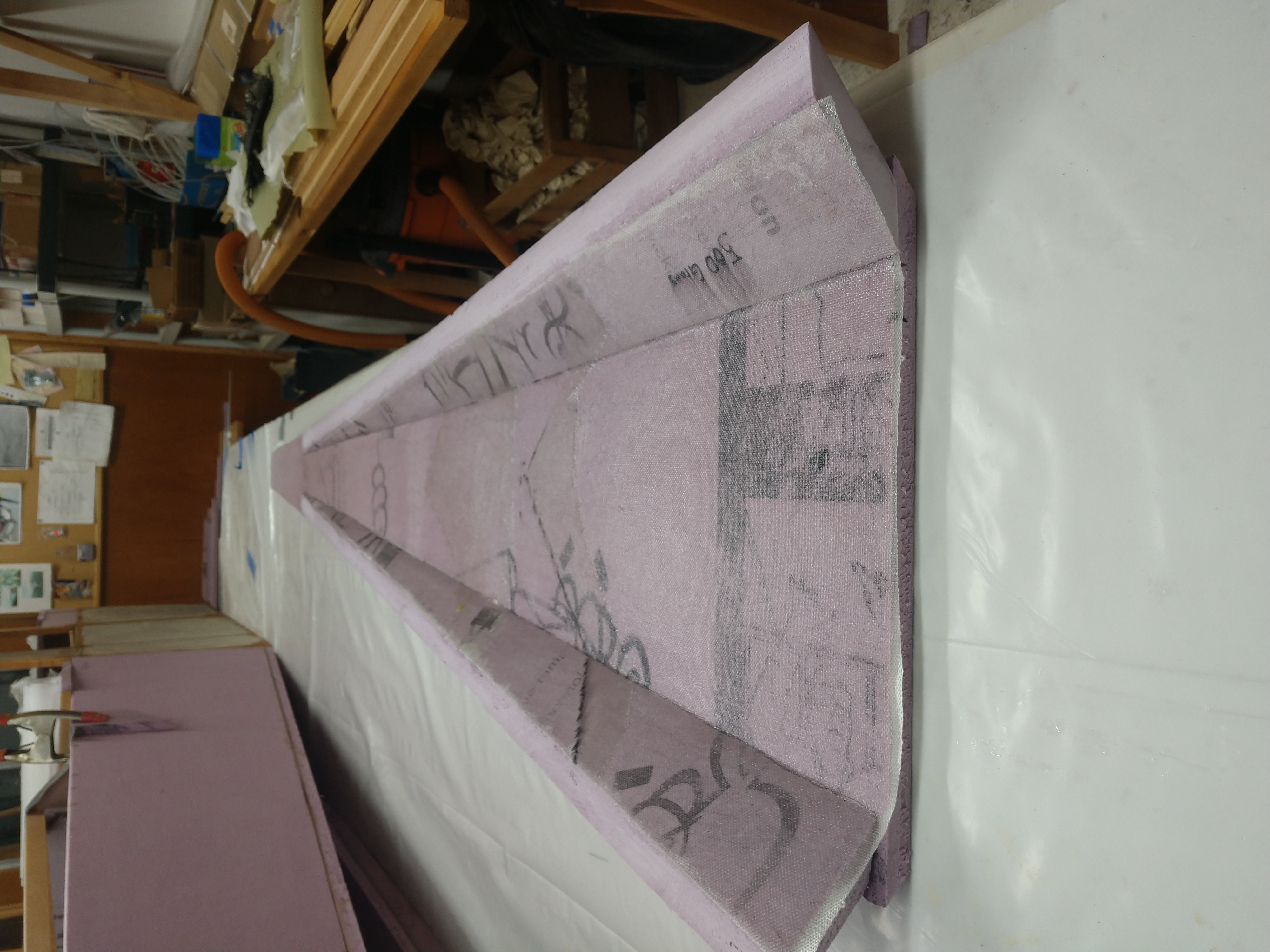
I laid duct tape on the bottom bevel edge it protect it from the layer on
interior fiber glass and it trimmed out just fine.
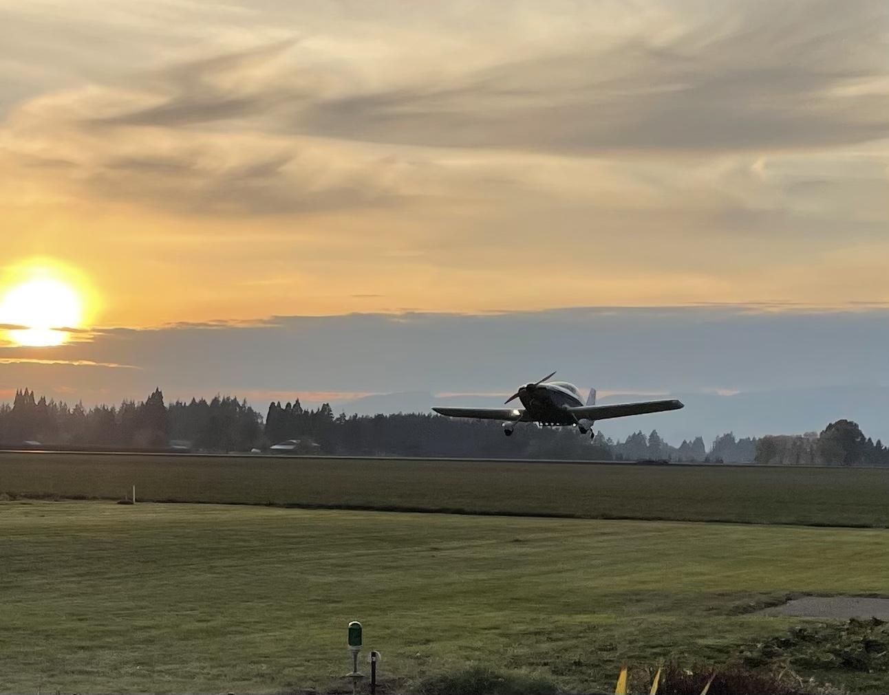
I then took the entire summer off to camp, work on my
KR2S to be ready for a
KitPlanes magazine article, and eventually
fly it to the KR Gathering in
Illinois.
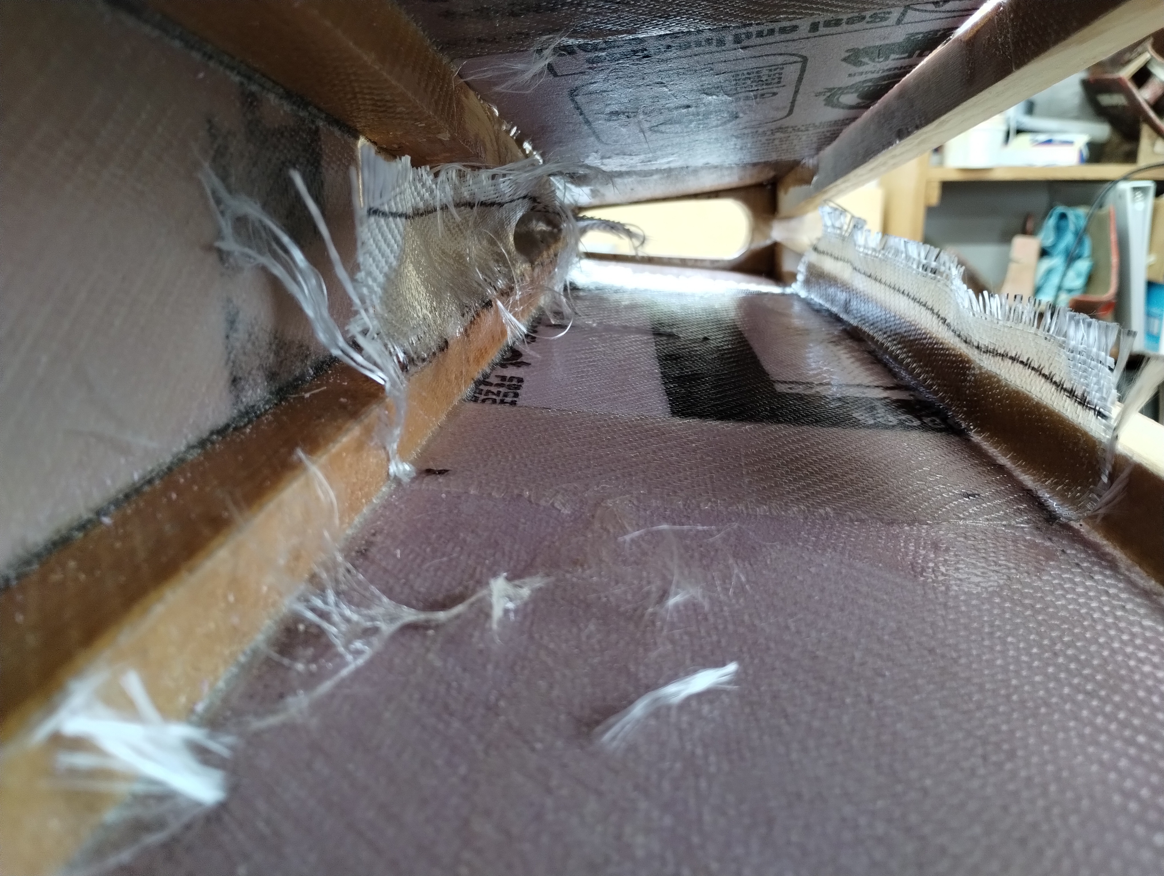
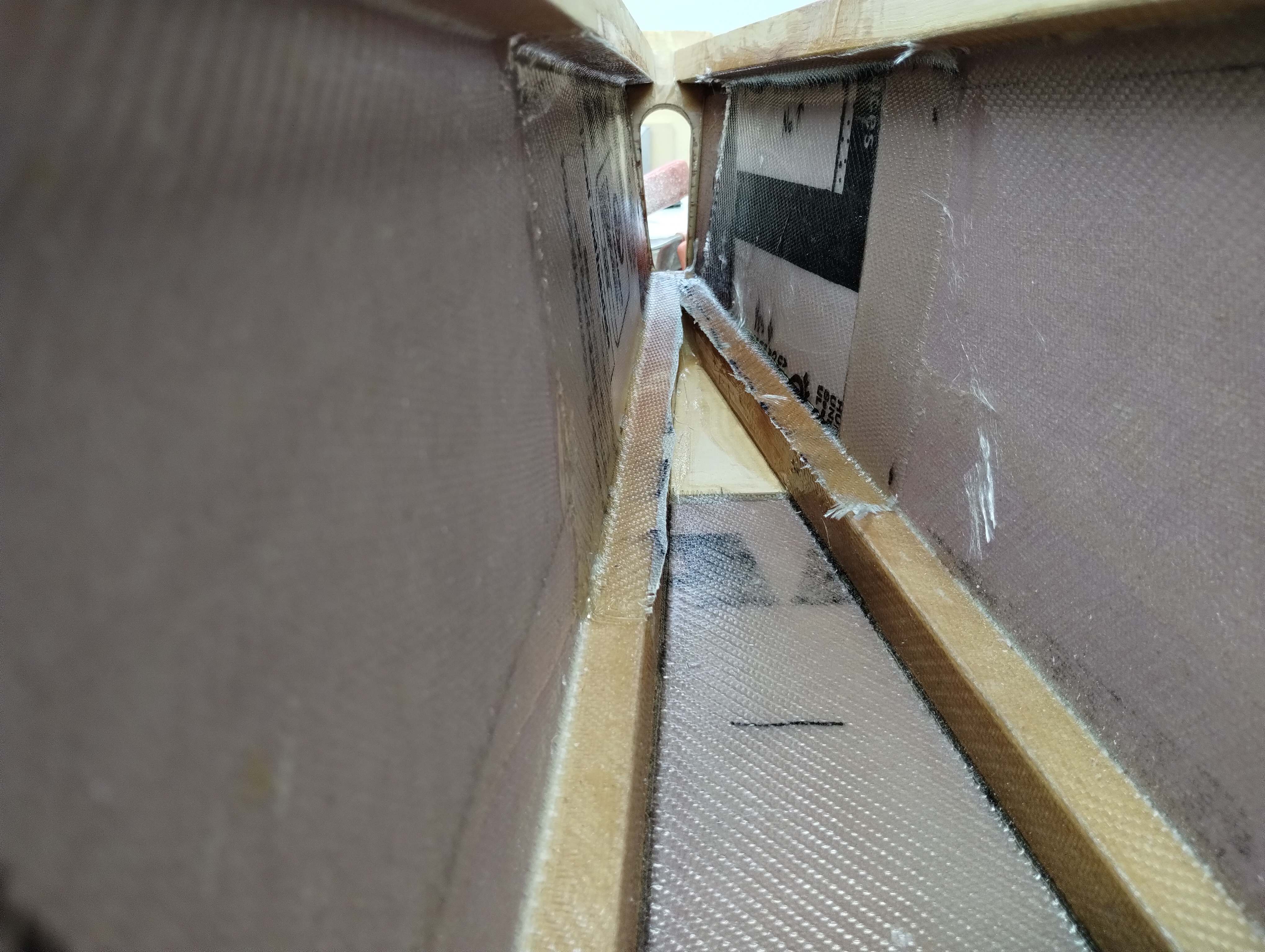
I don't like the limited glue contact between the longerons and the tail
plate. I made plywood gussets to increase the contact surfaces further tying
them and the spring plate into contact. Of course this required fitting the XPS
to the aft most part of the empennage. They are under the tail plate. Some 5
minute epoxy mounts them into position.
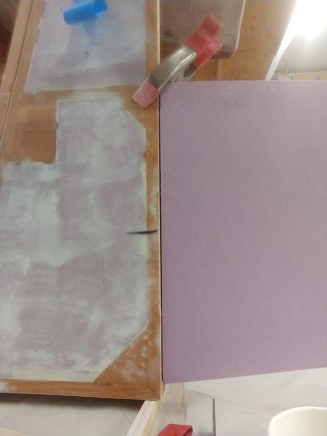
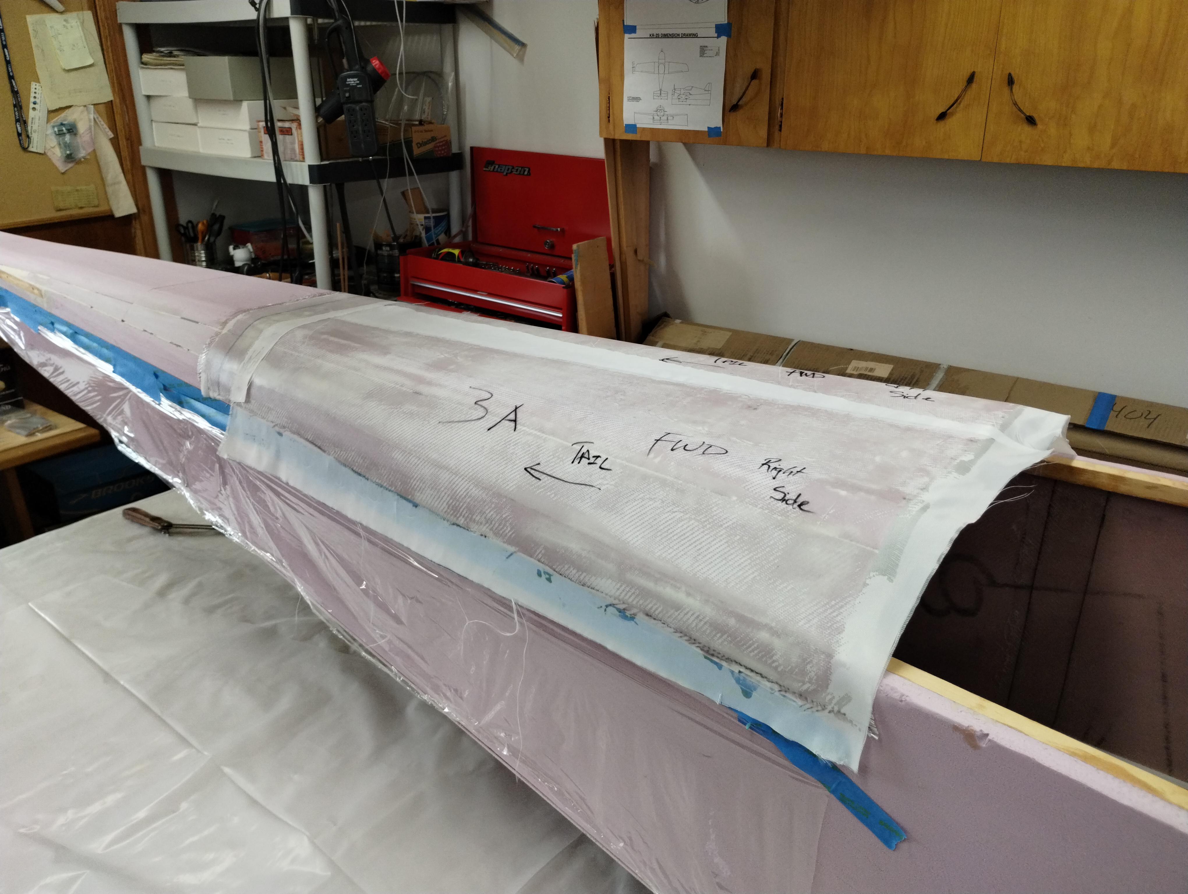
It gets glassed into place on the inside, trimmed at the resin green stage and
ends up looking like this when both sides were finished.
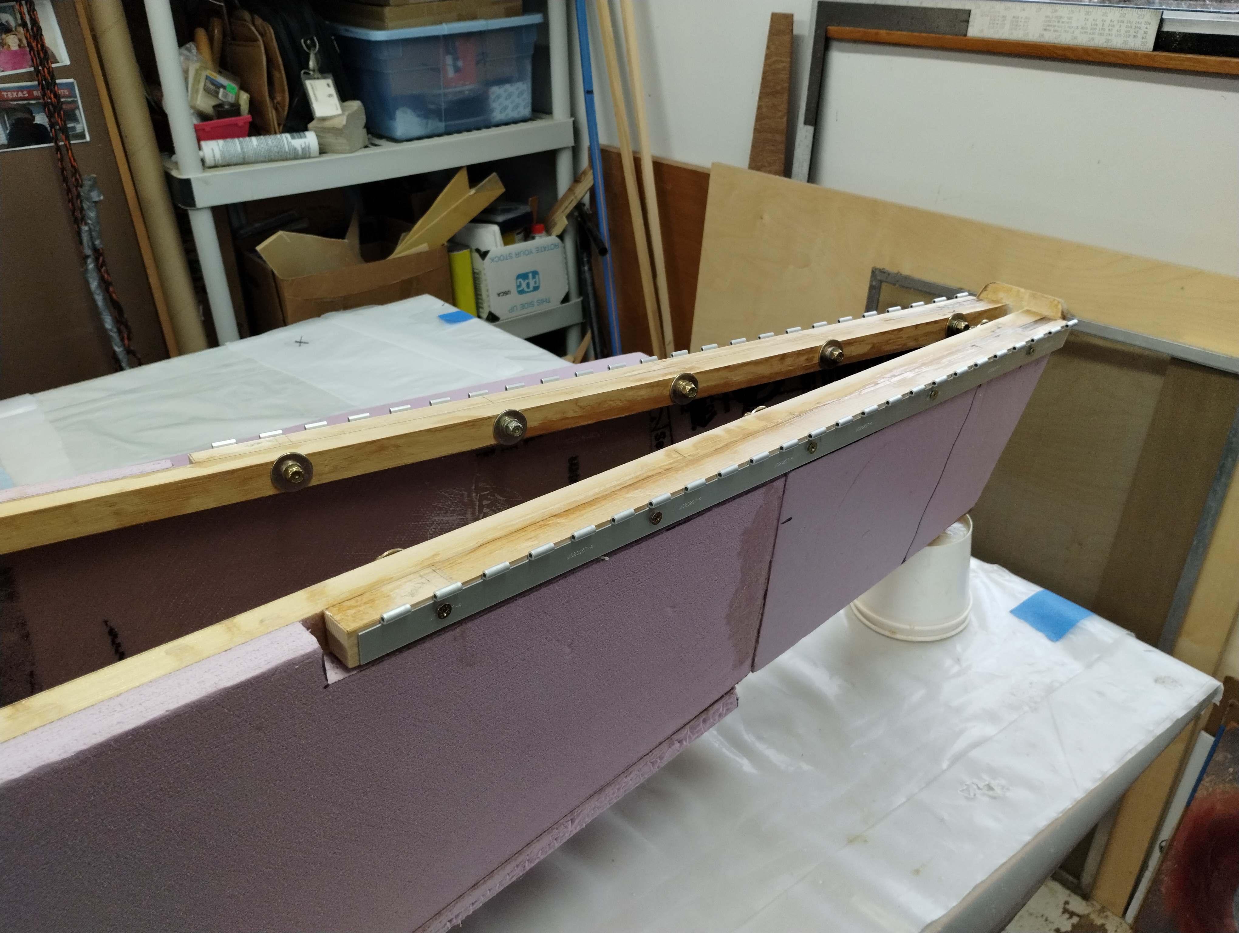
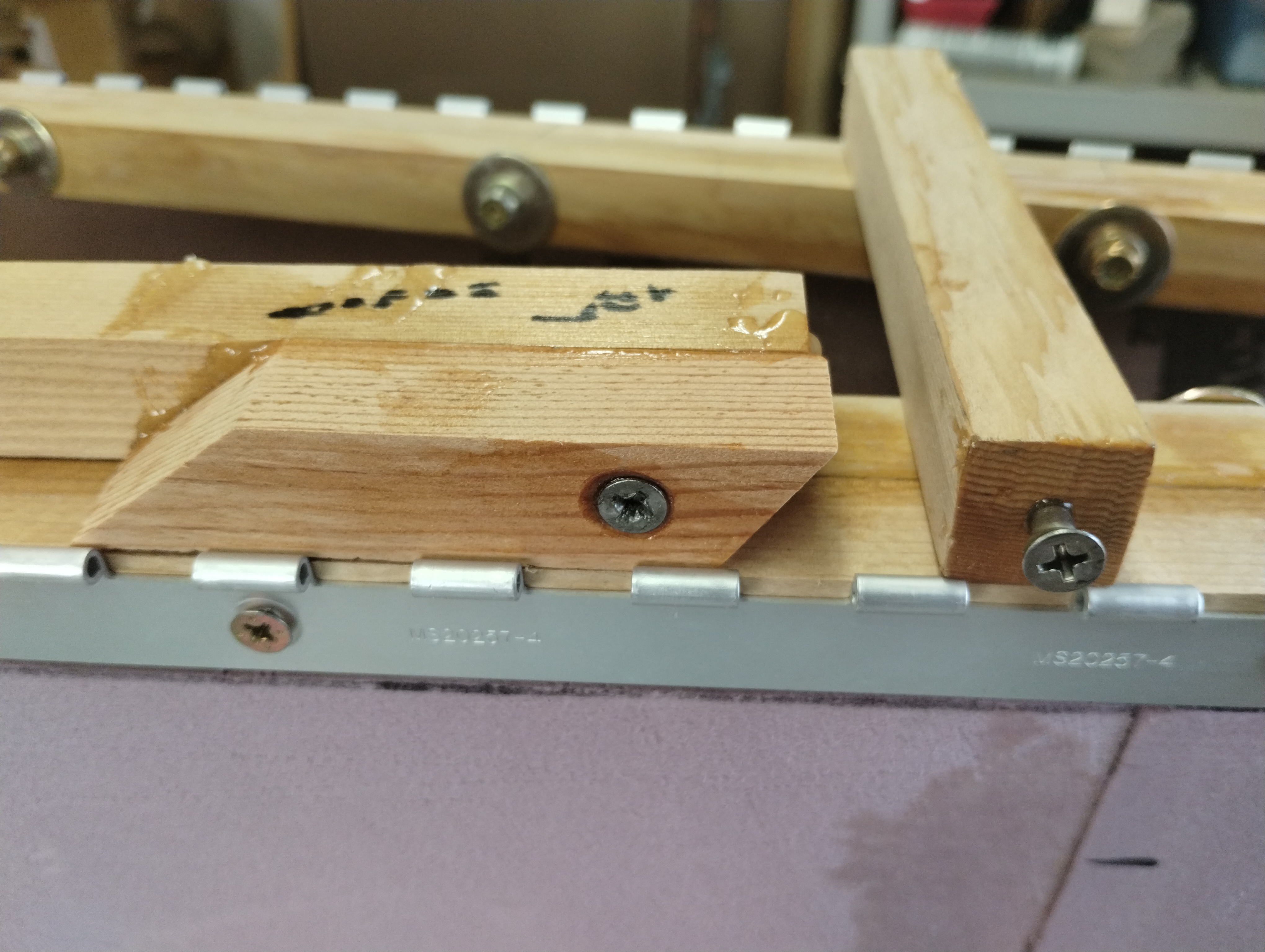
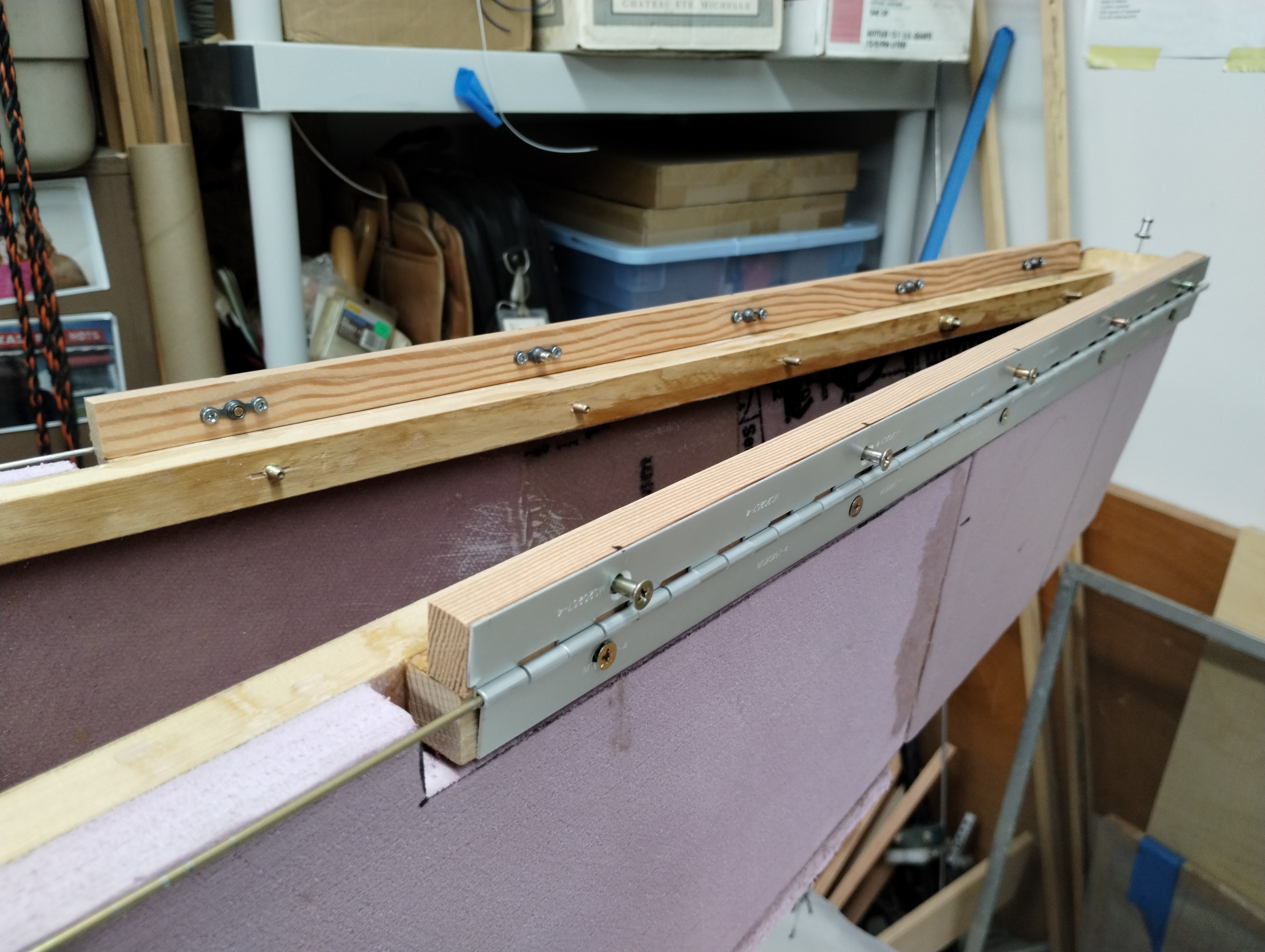
The horizontal stabilizer mounting blocks are fitted to go over the tail plate gussets and drilled for the hinge leaves. The spacer blocks were saturated with T88 epoxy and clamped into place. Then the hinge leaves were temporarily clamped into place and the longerons were match drilled and fit confirmed with temporary screws & washers. A microstop countersink (on loan from Dr. Melvin) will set the holes for 100% contact in the beveled screw heads when they arrive from Aircraft Spruce next week.
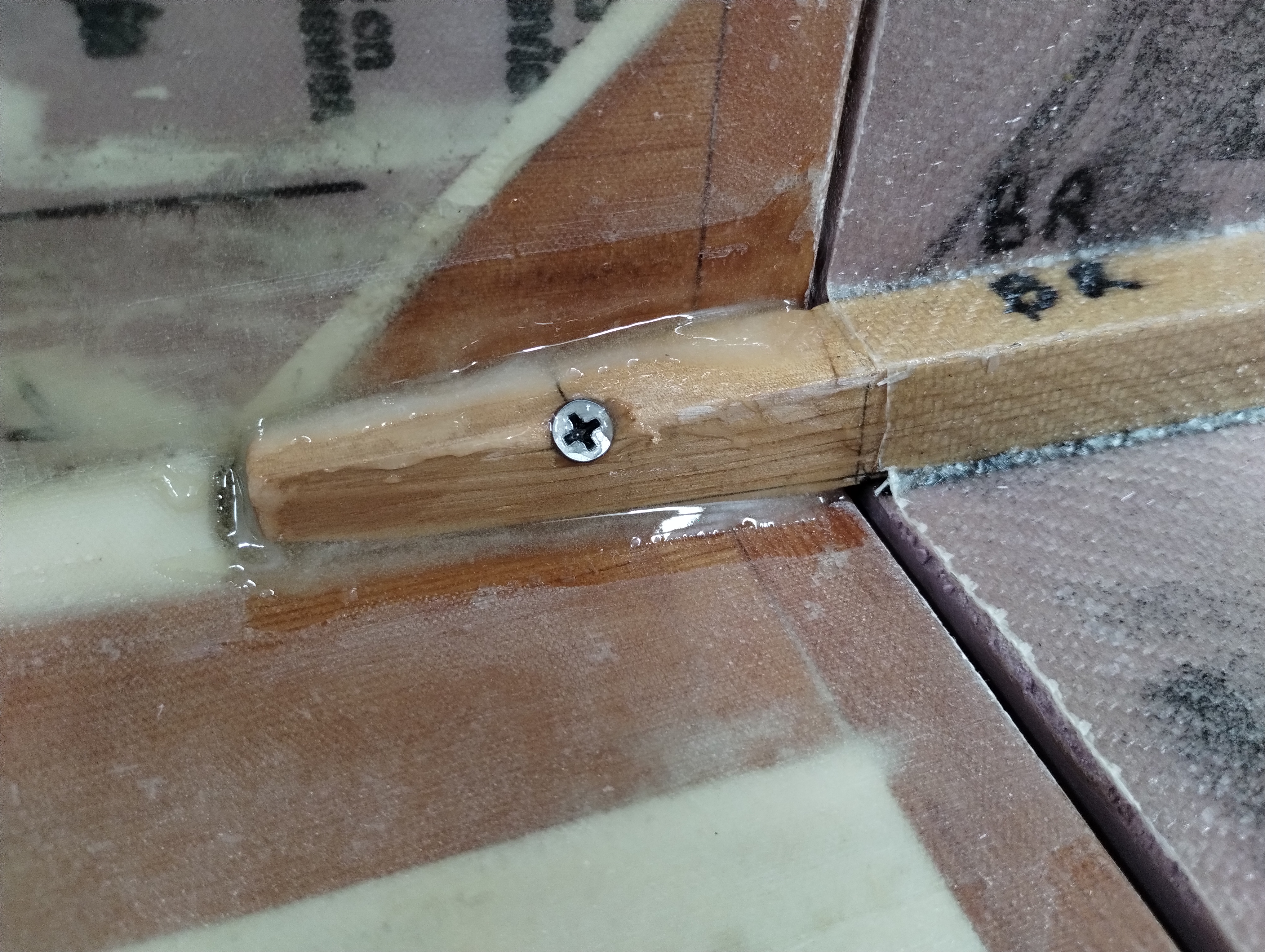
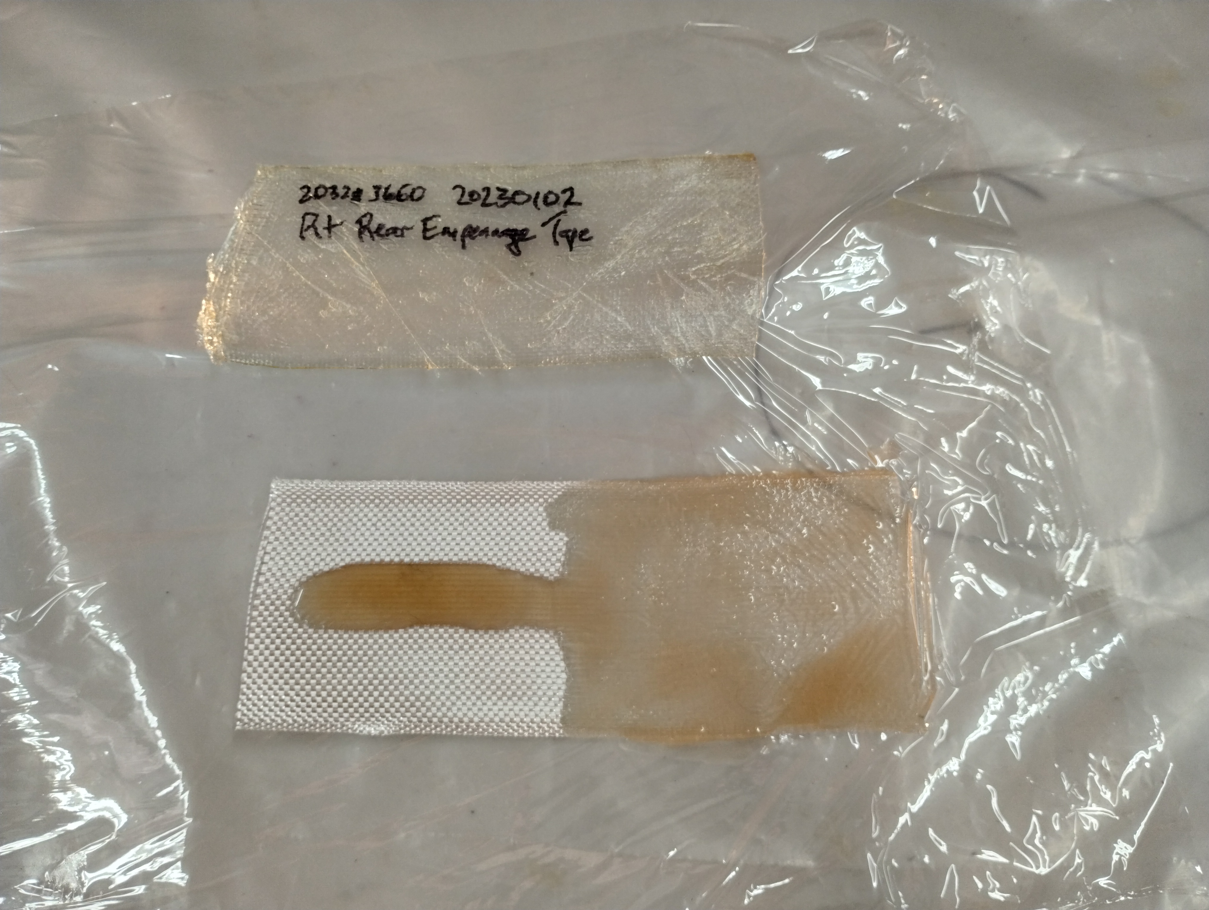
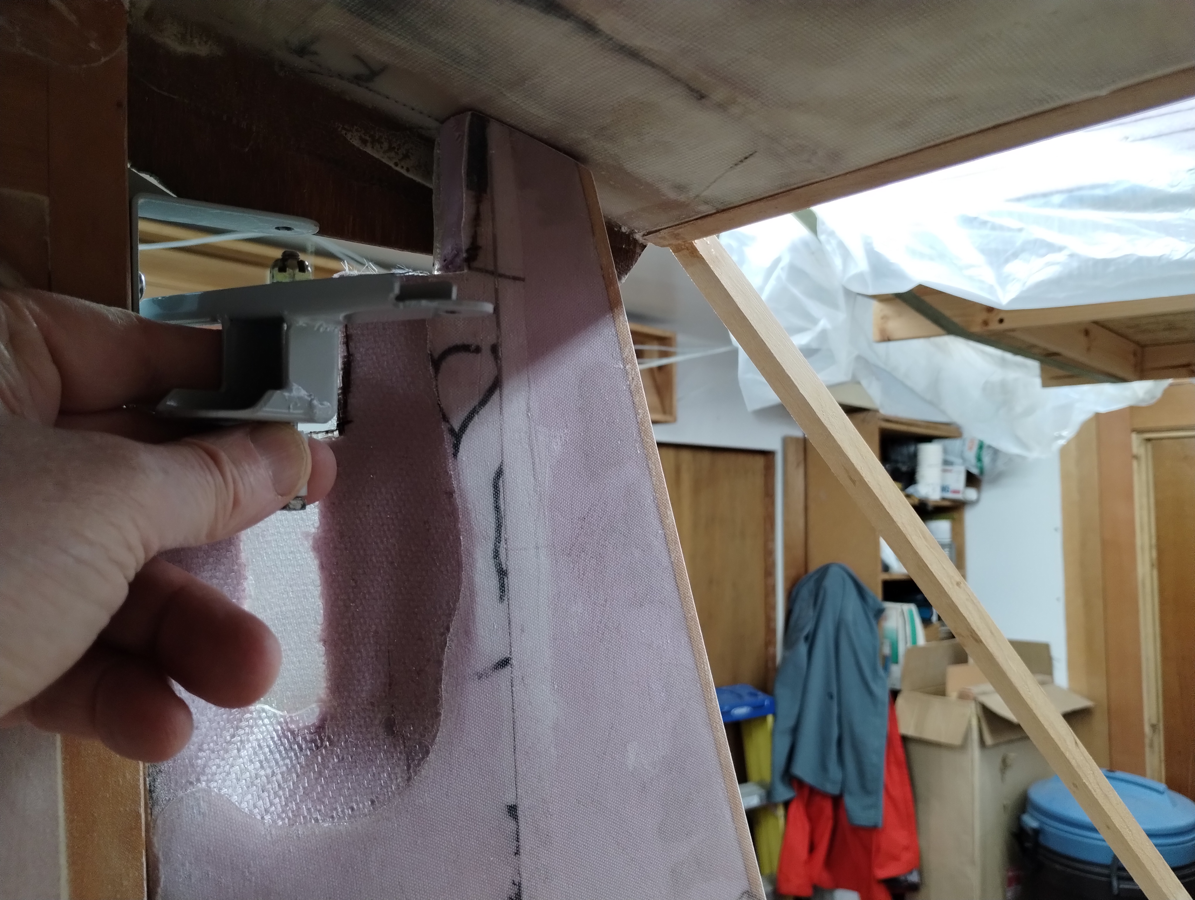
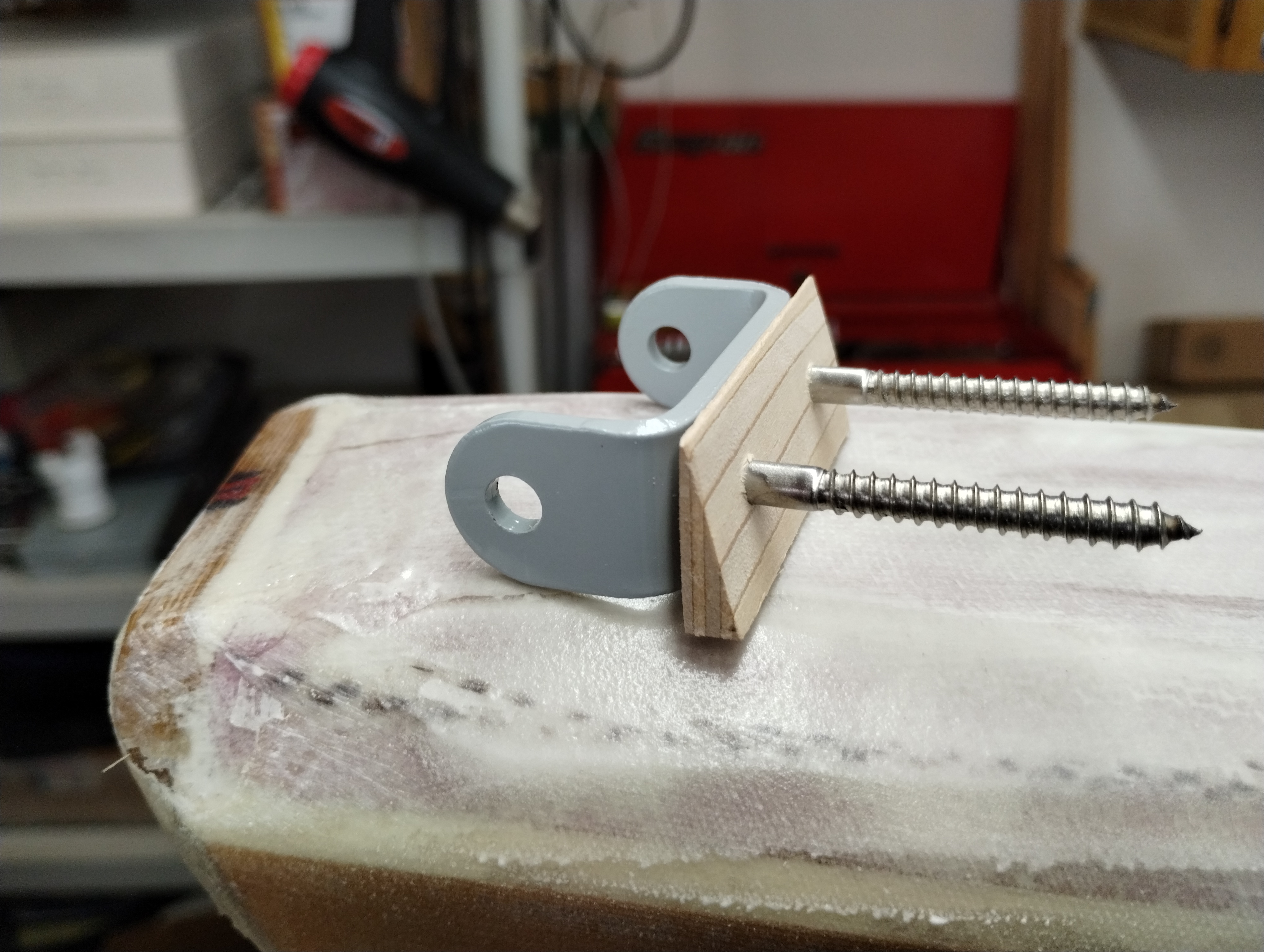
I wanted to test the stainless steel screws for retention and pullout;
the center elevator hinge point goes through the tail plate and into the upper
longerons end grain, and
the adjoined sample tests the empennage longerons screwing into the cabin walls.
Bottom line; they aren't going anywhere...
Finally time to bite the bullet and join the cabin and empennage.
A water level aligns the top line of the cabin top horizontal member to the
empennage top longeron at the tail plate;
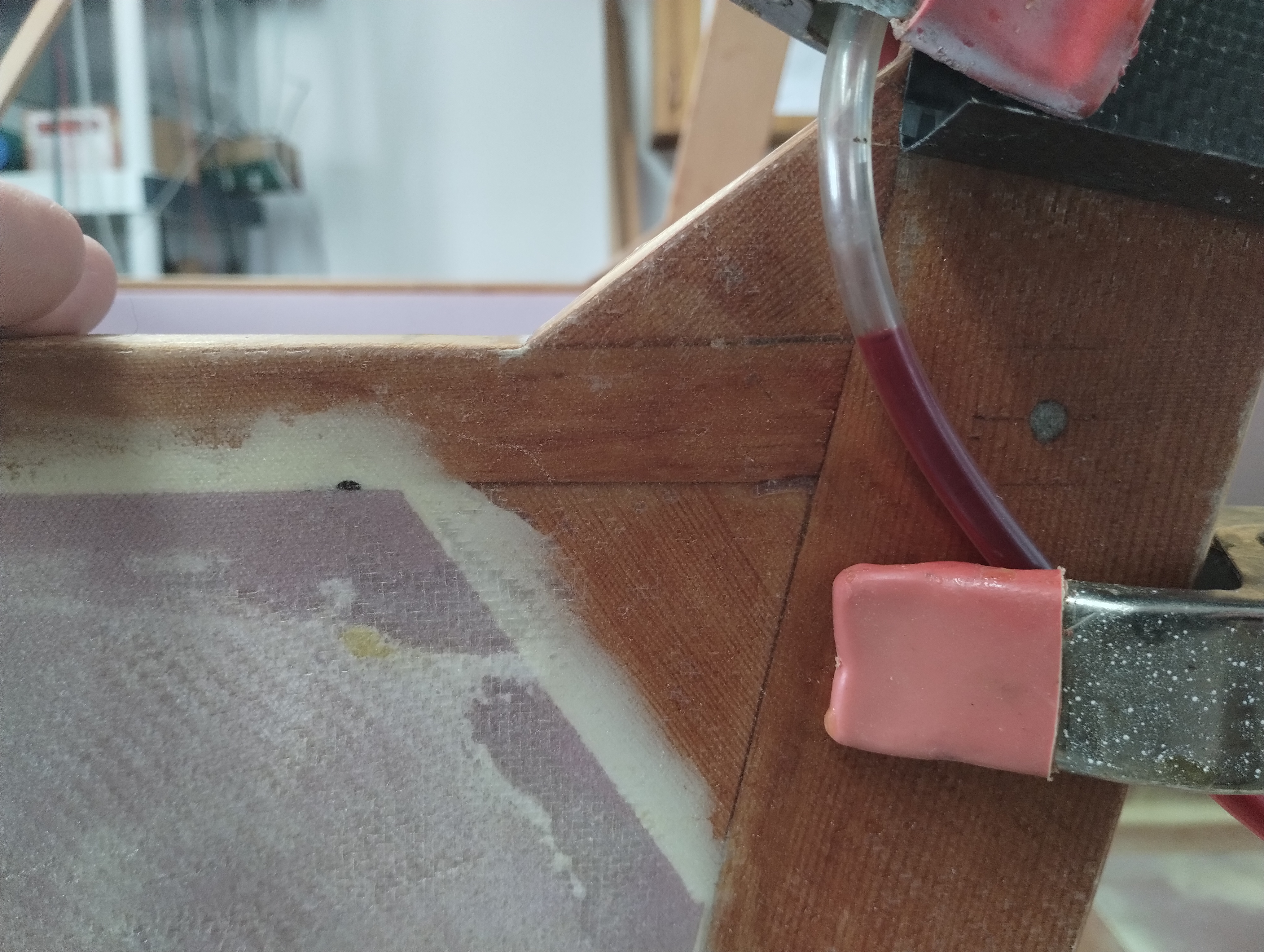
And the string aligns the centers for the tail plate, forward edge of the empennage, rear and forward cabin reference lines;
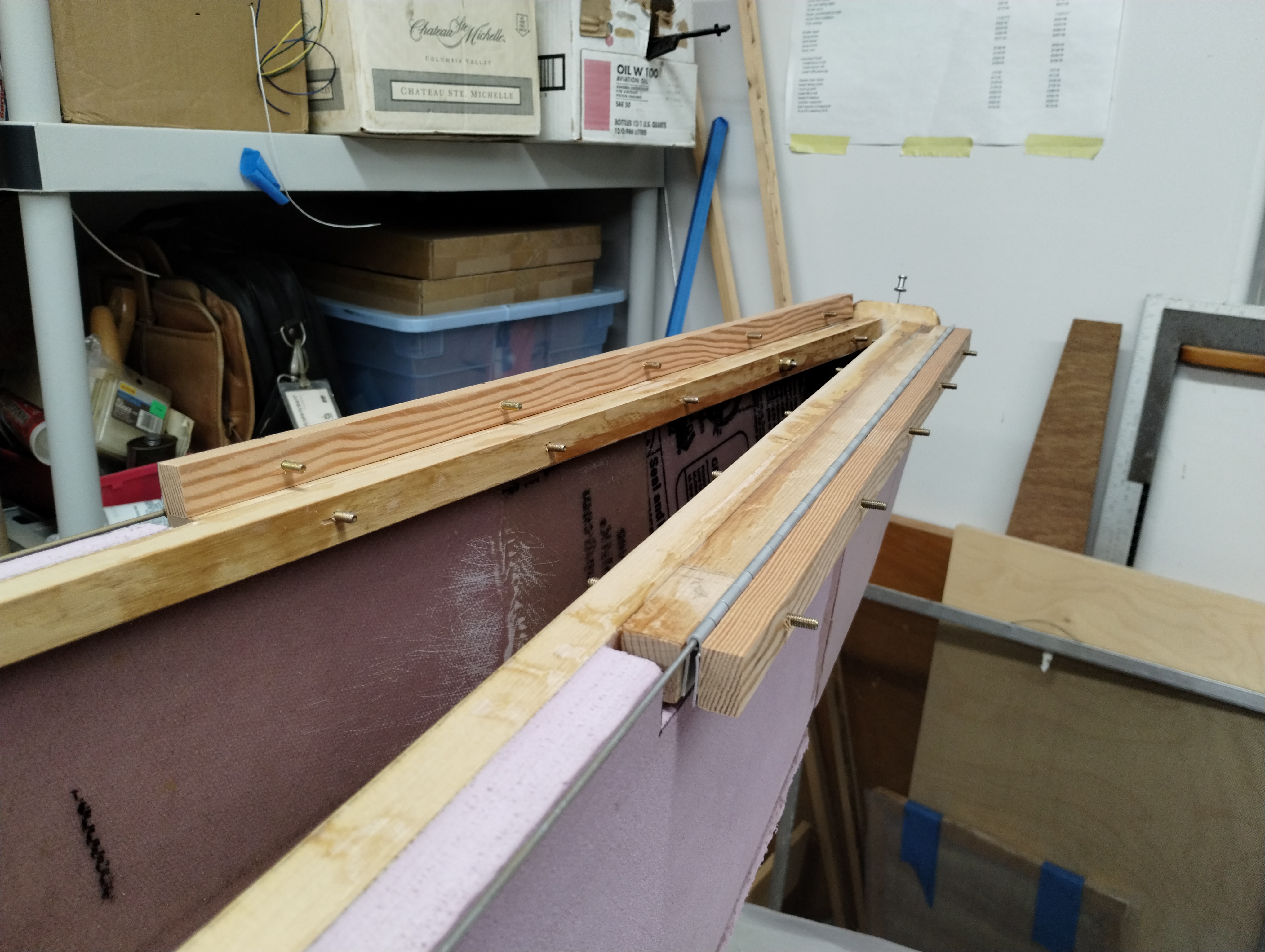
All lined up, it's time to clamp and drill for the screws. Note up at the top
of this page reference lines were drawn on the cabin aft upright posts and the
forward longeron tails. This guides the final alignment fore and aft of the
empennage to the cabin section.
Withdraw the screws, mix up T88 structural epoxy, butter up the contacting
surfaces and let it soak in to the wood and the screw holes for few minutes. Use
enough epoxy to get a mild squeeze out as you tighten the screws into final
torque.
And before your glue sets up, double check your lateral level cabin-to-tail
plate height!
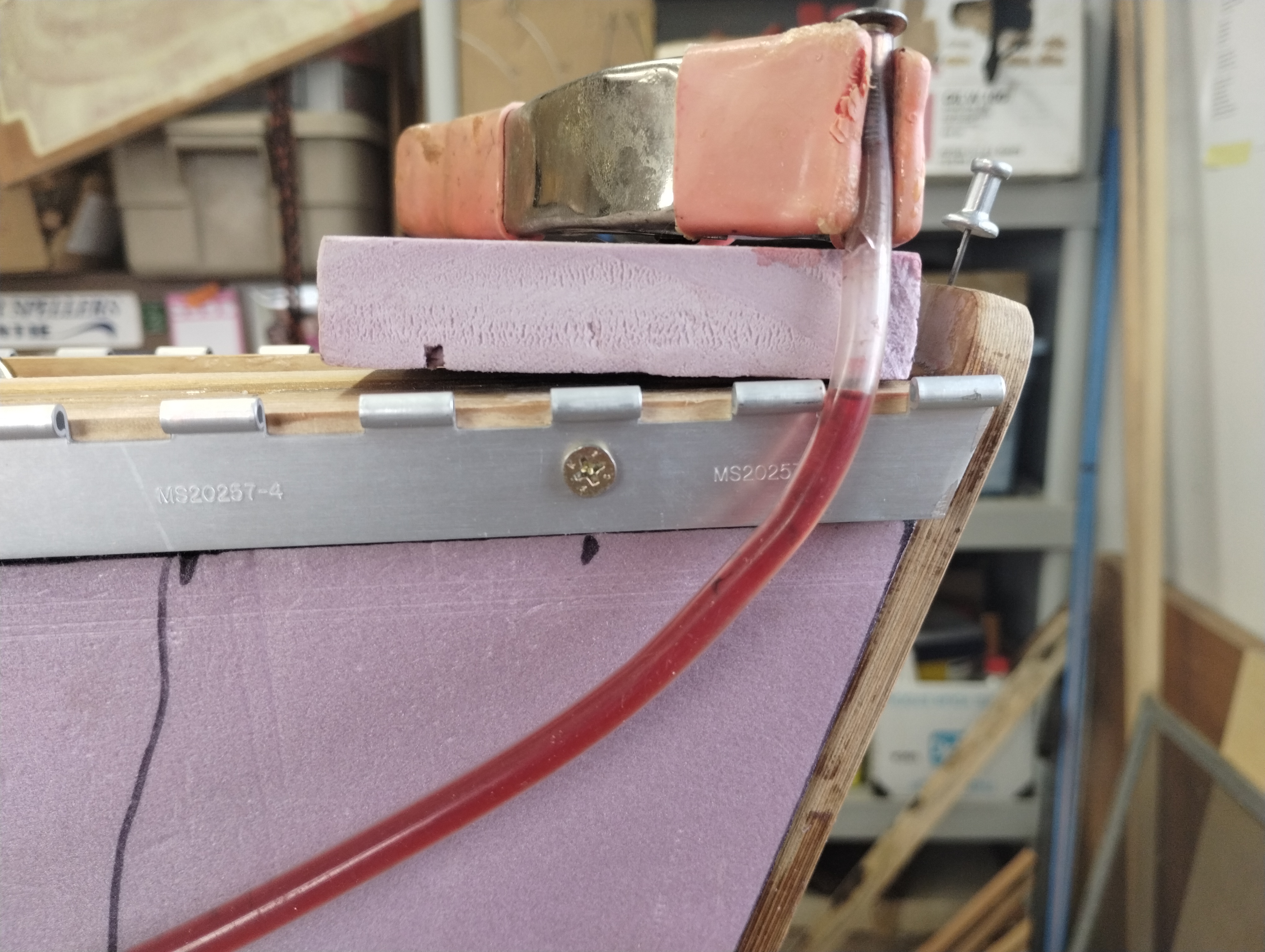
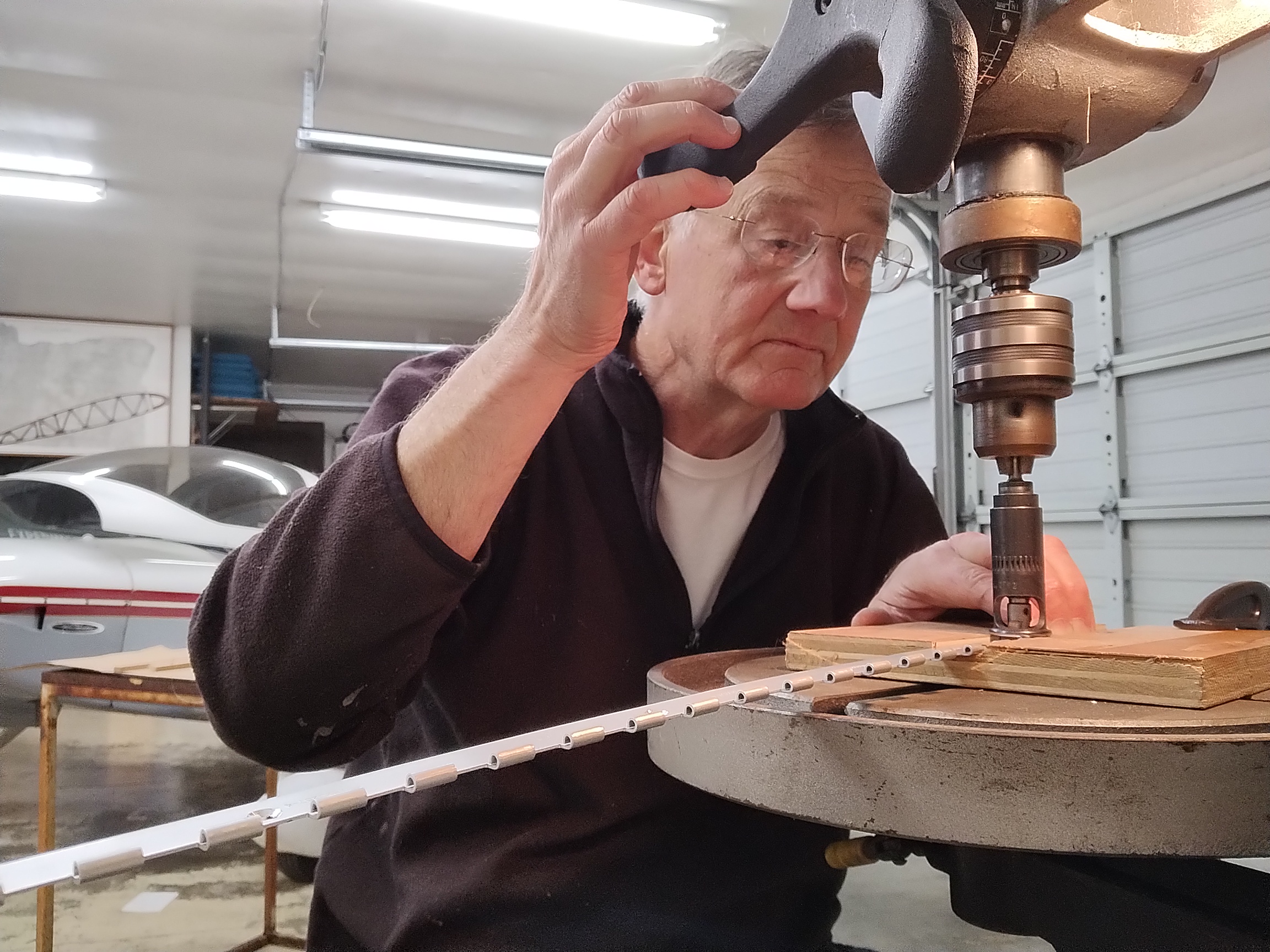
For easiest access, I drilled the horizontal stabilizer root ribs (1/2" x
3/4" stock) for the hinge sections before attaching the deck lid.
and countersunk the hinge leafs for the screws. Never get easier access than
right now. Thank you Dr. Melvin; that's a wonderful tool!
Now fit the plate nuts because this rib will be covered over with XPS &
fiberglass.
Attaching the deck lid at full length would about be impossible to lay up the
3" FG tape over the lid-to-longeron seams. I cut mine at about the 3' mark
forward of the tail plate.
Mixed up AeroPoxy with some micro to make putty and glued it into place. Bicycle
tubes make fantastic clamps!
When that cures, turn the fuselage onto a side, brush on straight AeroPoxy
over the 3" width from the longeron sides and up onto the deck lid.

I wet out the tape on a sheet of plastic and pulled it into position, used the
brush to squeegee into contact and pulled off the plastic sheet. Neat and sweet.
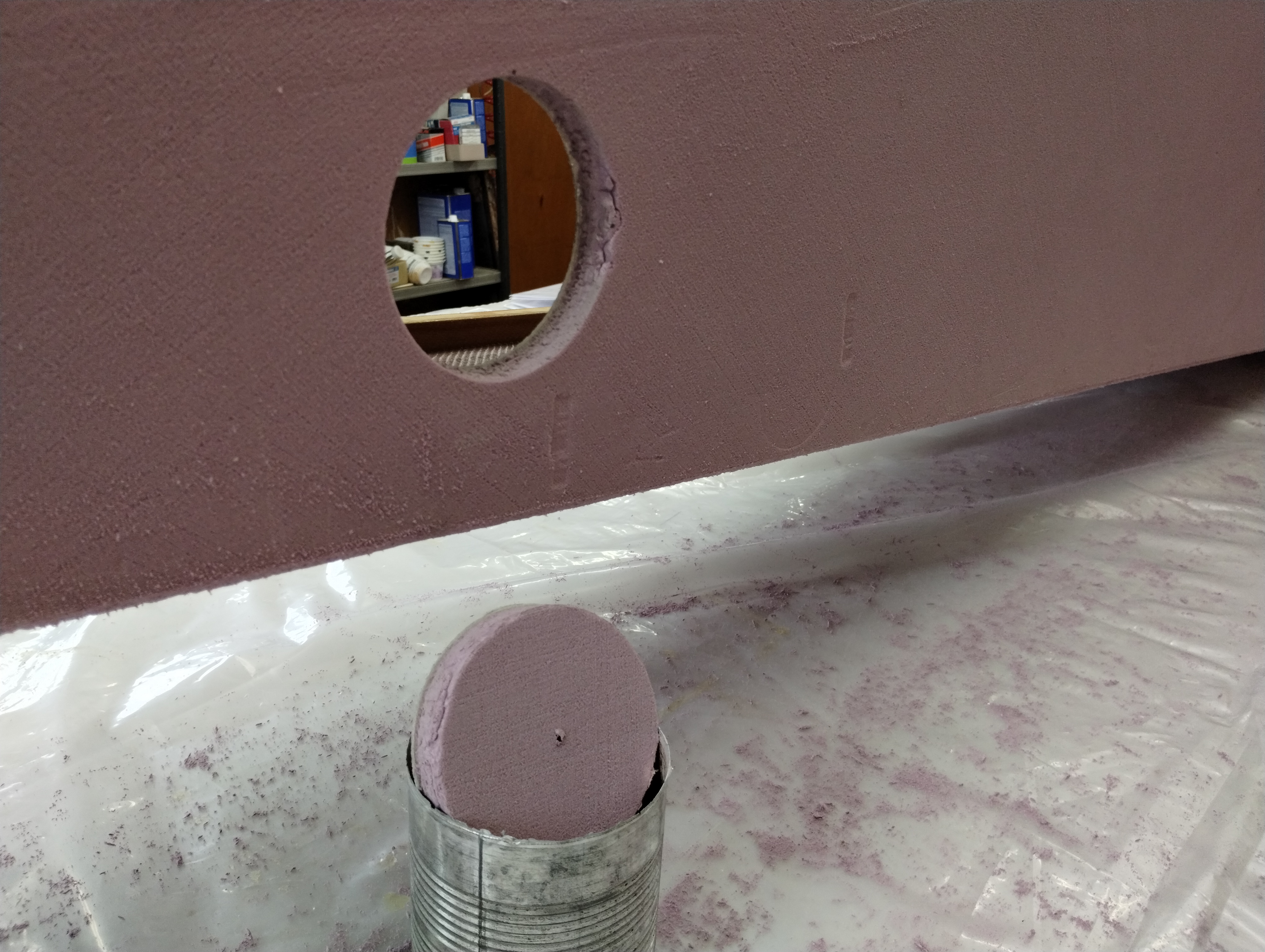
To thread nuts onto the inboard horizontal stabilizer leaf screws, you'll
need a hand hole. Marvin designed it on the bottom side of the fuselage. Oscar
used a fly-cutter in a drill. I cheated. This is a #4 tin can. I made a sharp
edge on it and placed it on the XPS. Rotating back and forth it cut through the
XPS very cleanly and, eventually, through the inner FG skin. Voilà, a hand hole.
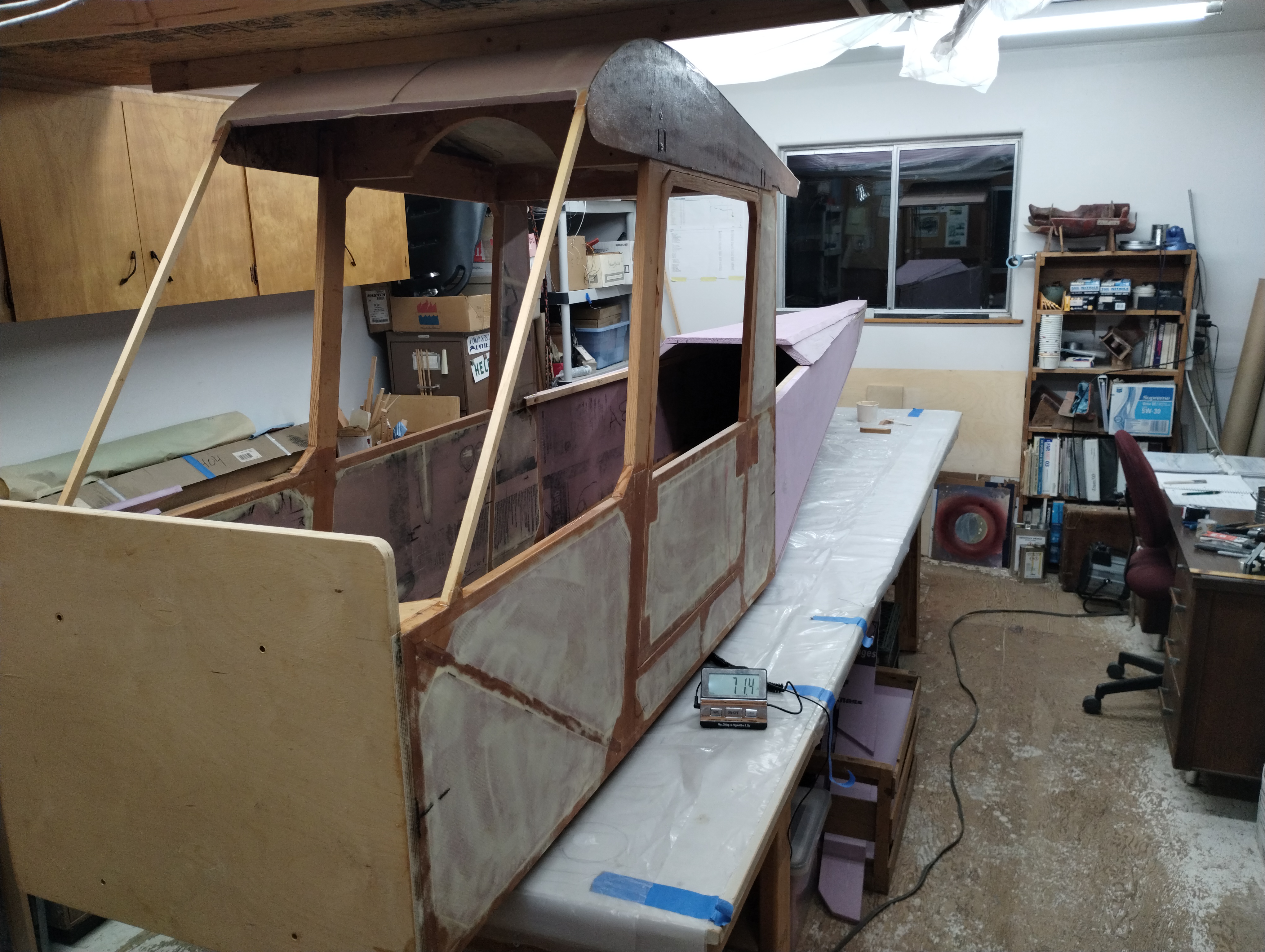
Total weight so far; 71.4#
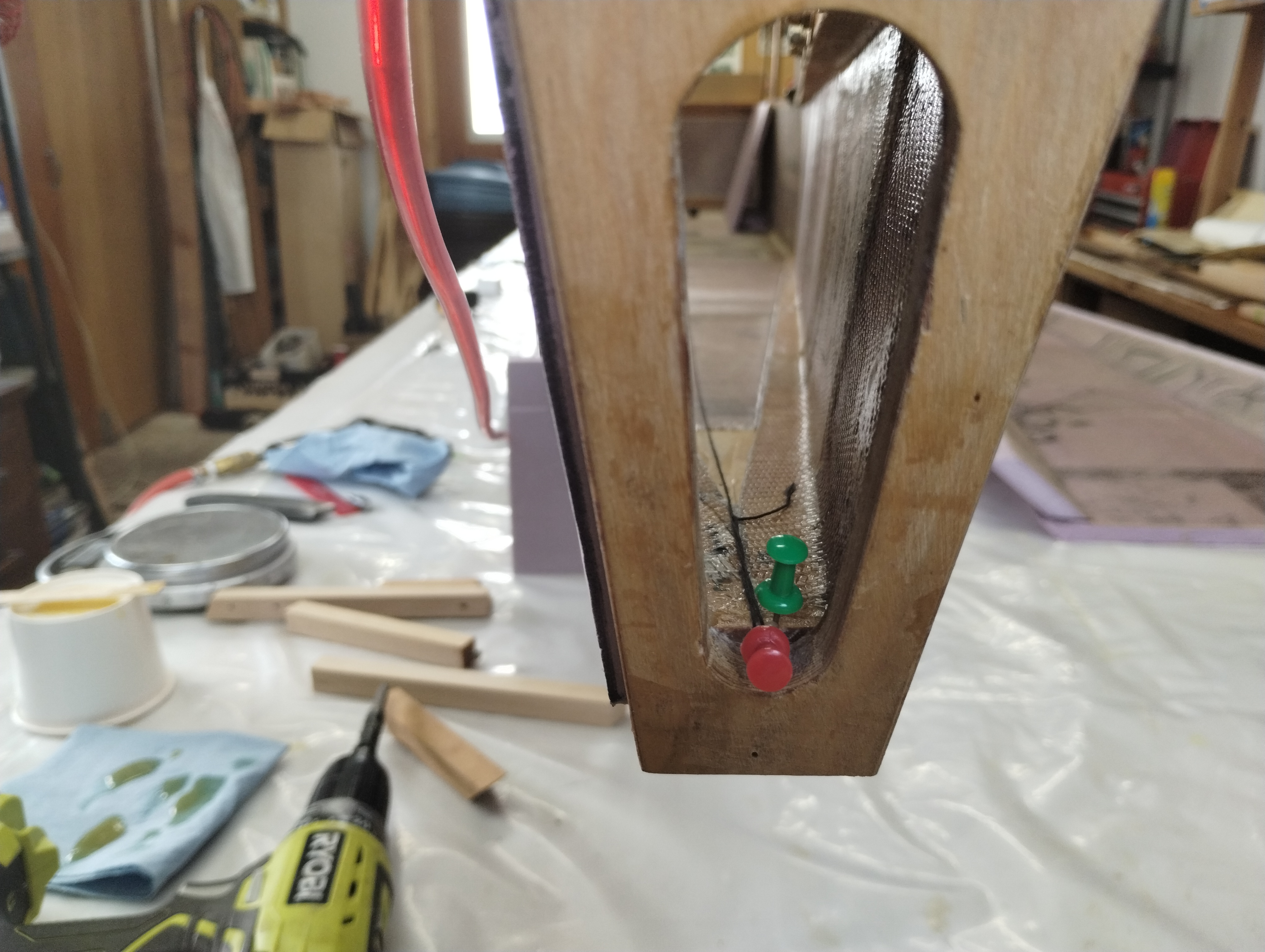
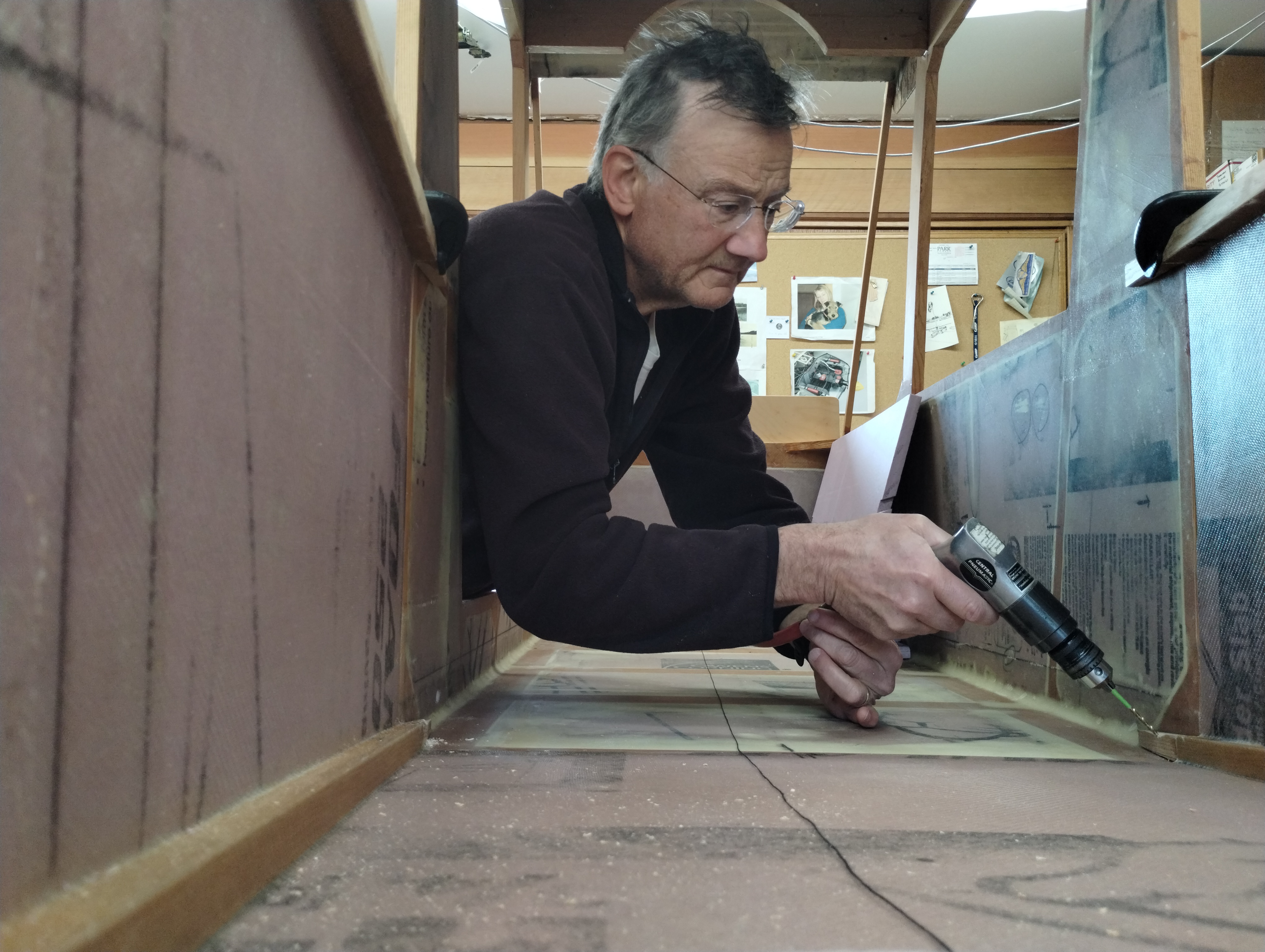
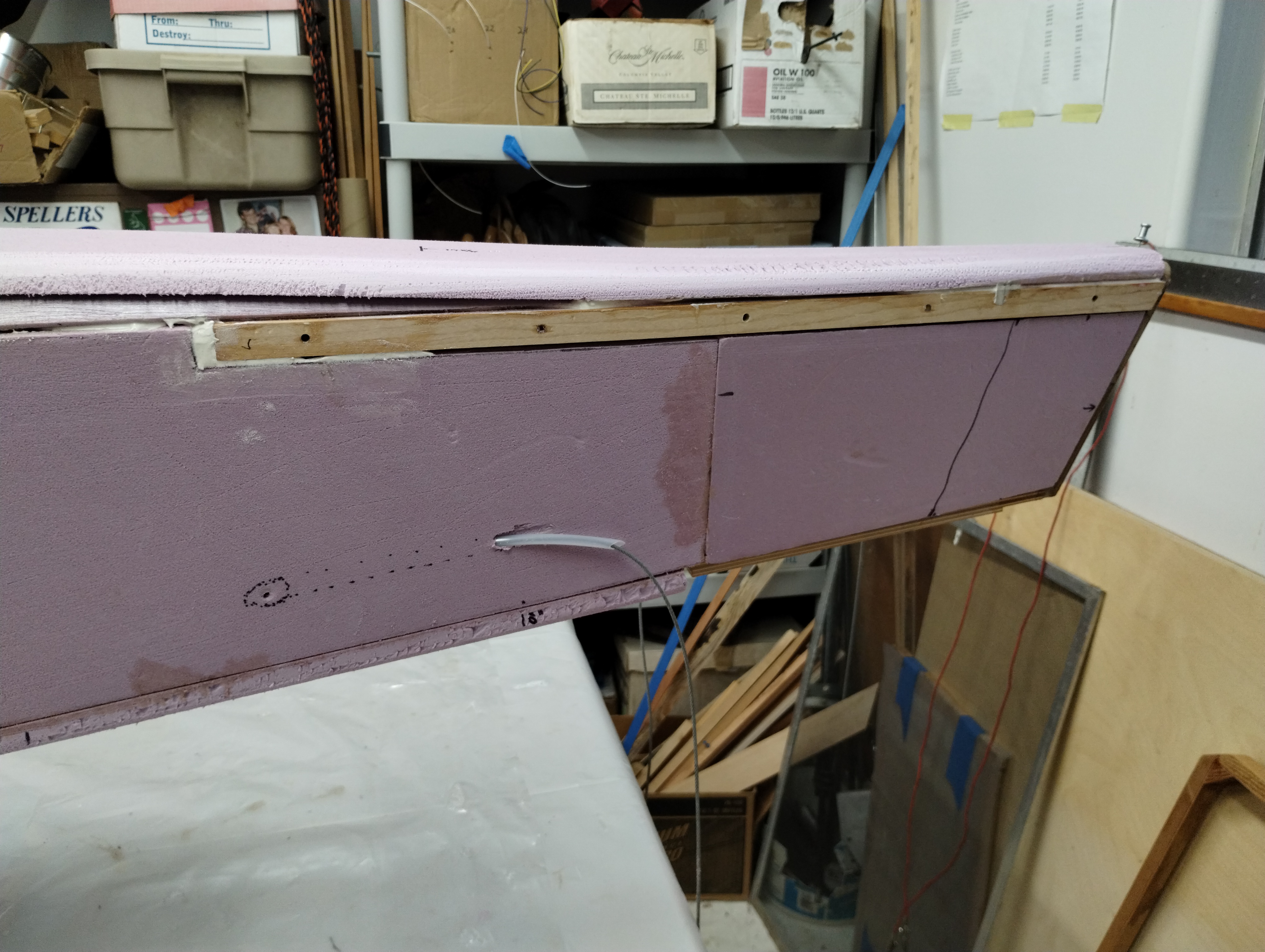
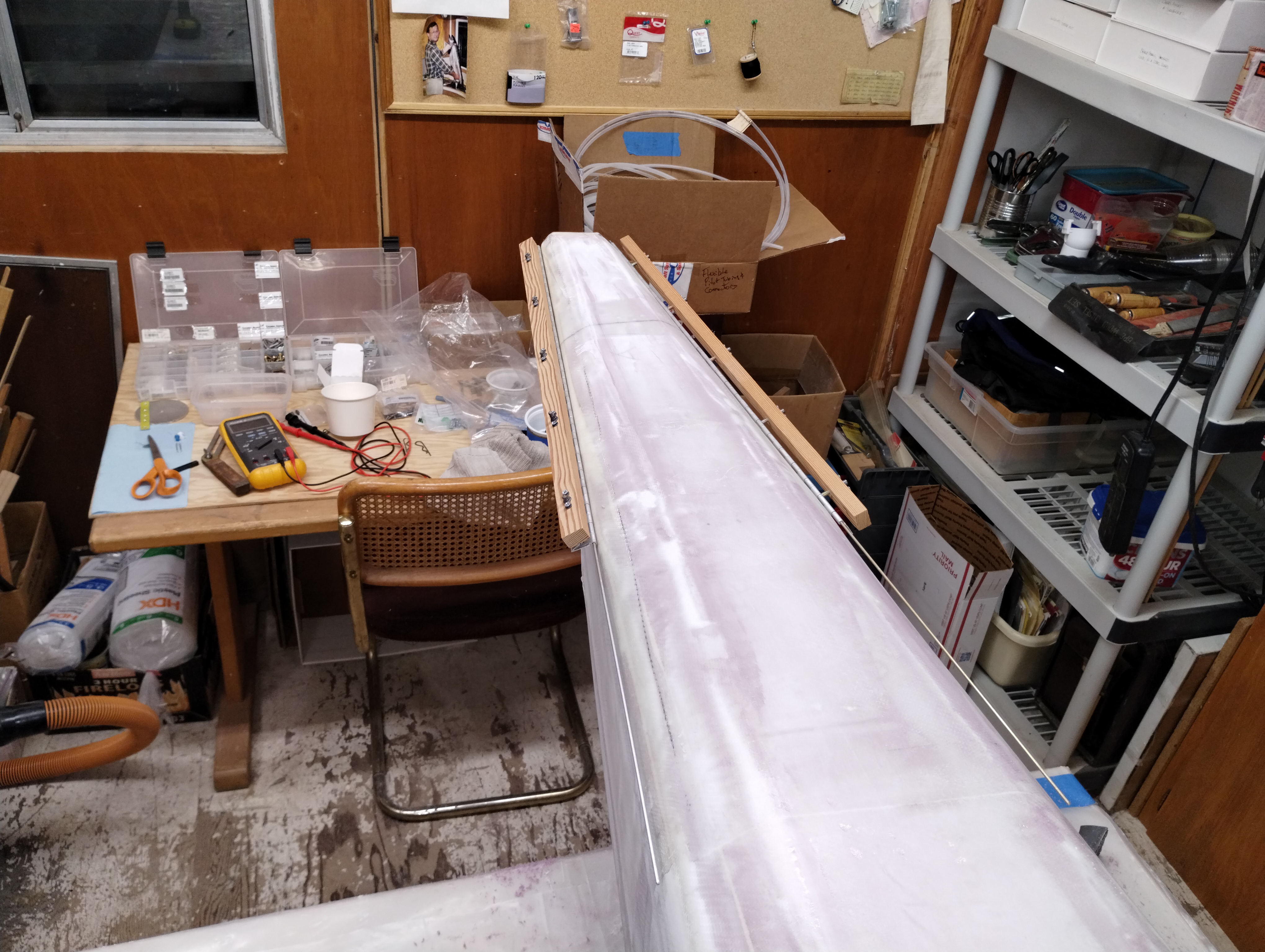
Before the rest of the rear deck gets glued into position, I ran the rudder
cables and guide tubes. You can see the exit path I marked up on the exterior as
my drilling guide.
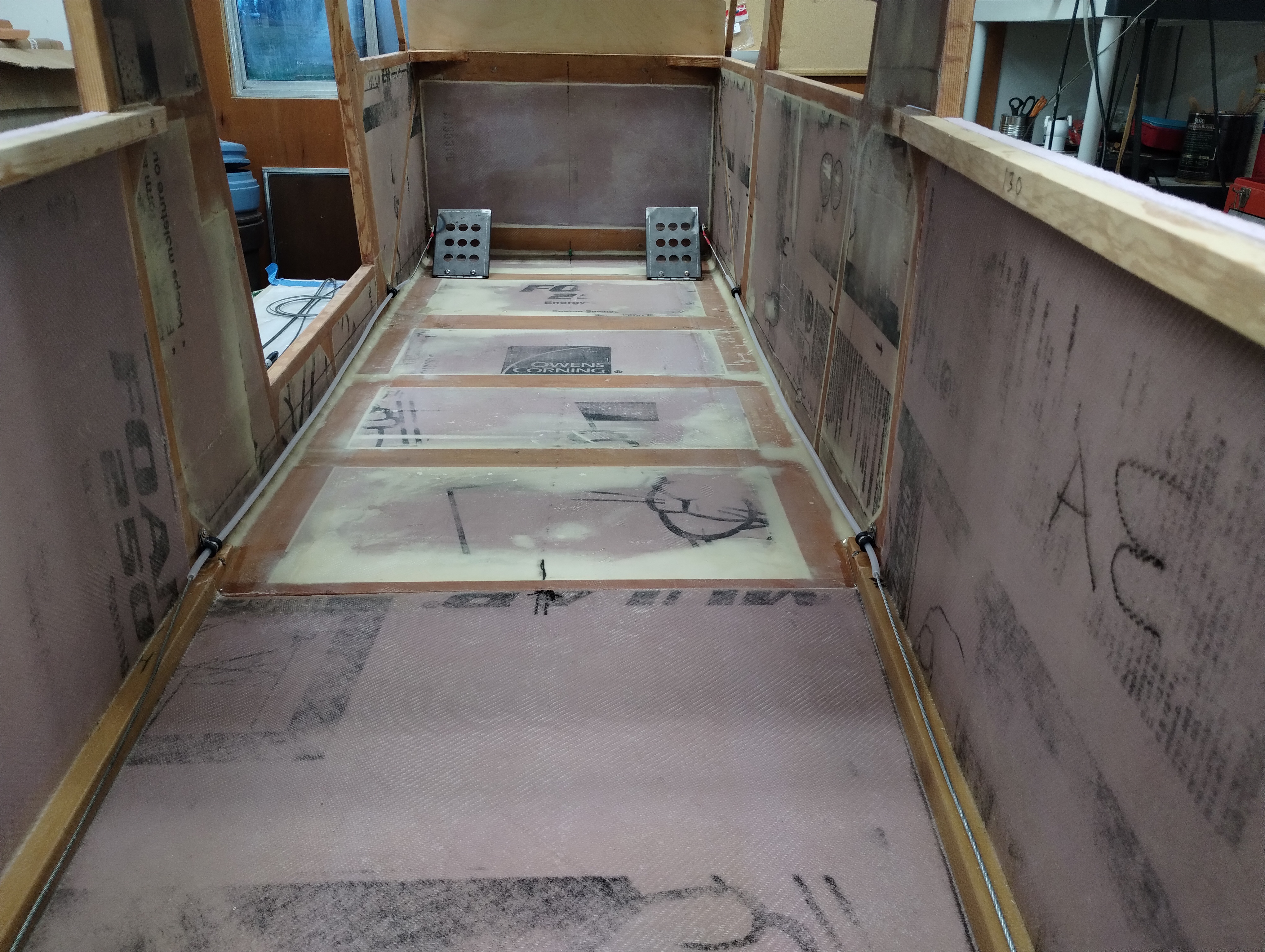
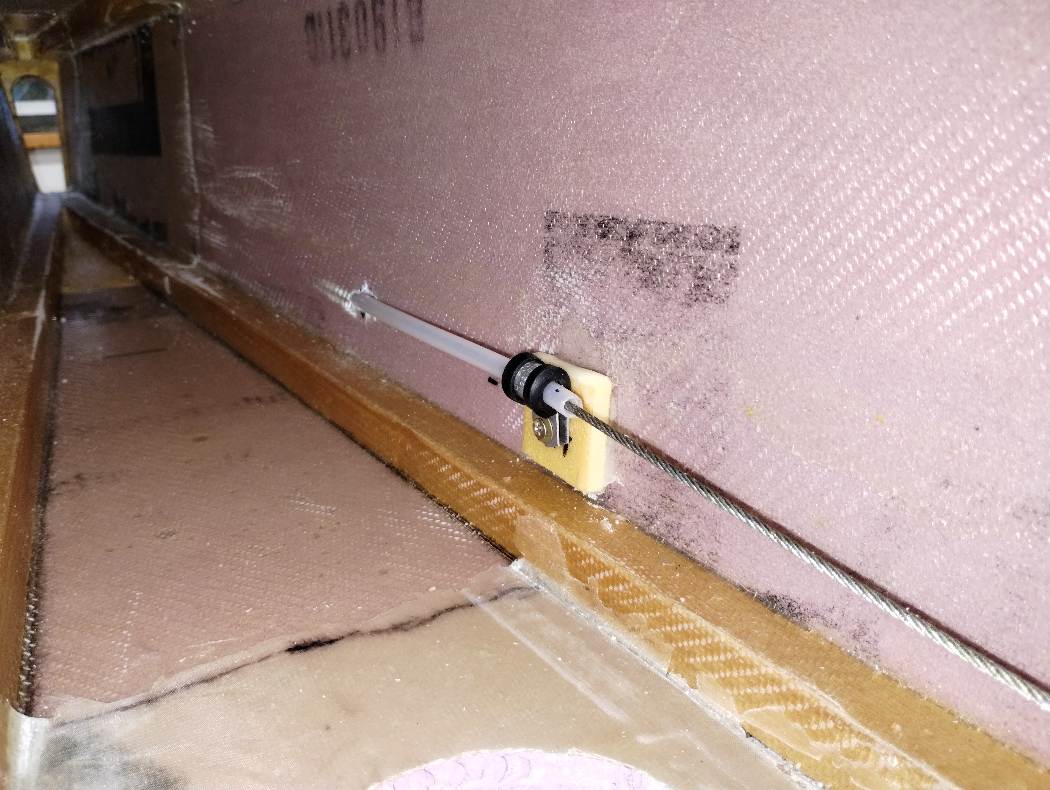
I installed P-clamps with buried T-nuts to hold the aft tubes in place
Finally time to install the forward part of the aft deck. This shows
buttering up the contacting surfaces with the AeroPoxy/ micro putty mixture.
Marvin calls this "paste."
Don't forget to install the inside 3" tapes on this lid section as detailed
above...
This shows drawing reference marks to ensure my tapering the tail deck is as
close to symmetrical as possible.
At this time I'm filling little gaps and scratches in the XPS, the stage Marvin calls "surface finish tip" prior to laying on the exterior fiberglass. That'll be a milestone...
November 2023 Update:
Well, that was a major delay. I thought I'd have to
make everything "just perfect" before getting on with applying the exterior FG.
I finally realized I'm not aiming for "perfect" because I'll never get "done"
and that's unacceptable.
Marvin built what I'm thinking of as a
"Proof Of Concept" airplane. Much the same as Ken Rand's
first KR1. People who've seen Ken & Stu's initial work effort described it a "a
little rough." I can put some of Marvin's finish work in the same category. It
was obviously airworthy as he and Justin Drake flew it many, many hours.
I'm aiming a bit higher on the finish work. I'm trying to simplify the
construction. I'm thinking of mine as a
"Design Prototype." Marvin proved it can be done and it
WILL fly. I'm wanting to show following his instructions yields another copy of
his design, if with a few minor tweaks. Marvin built the M-19. I expect mine
will be the M-19b...
December 21, 2023 Update
I glassed the empennage finally.
I clearanced the "tail wing" hinge mount holes and trial fit the H stab hinge
leafs successfully. That's all good.
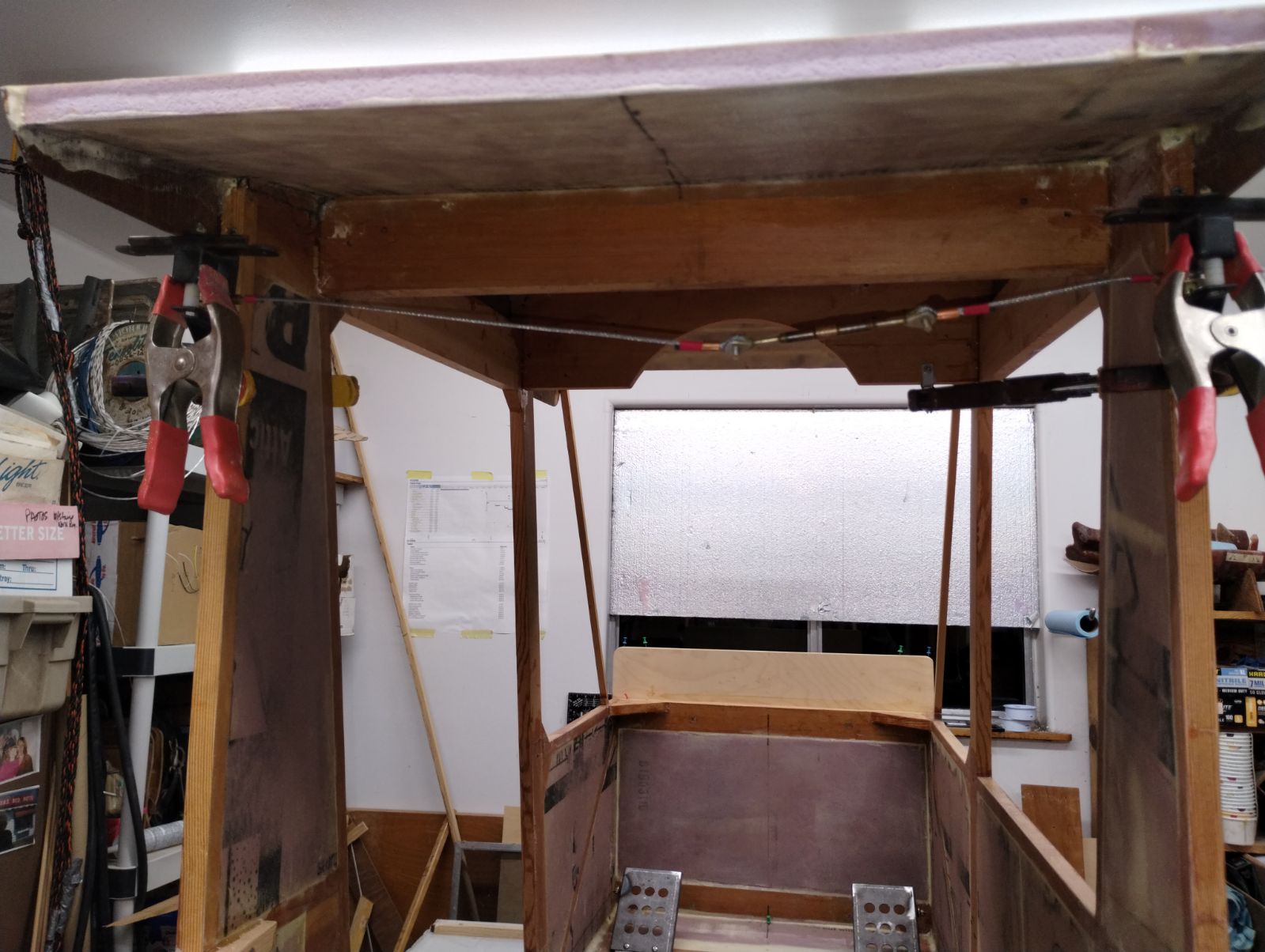
I assembled the aileron belcrank components and drilled the cabin rear posts
to mount them. I built the crossover cable and stress tested it by standing on
it in tension. All good there.
Looking at Marvin's and Oscar's fuselages I noticed the forward window
framing was upsized to 3/4"x1/2". One of the few errors I've found in the plans
and construction manual. I tore out the front frames, moved those sticks to rear
and replaced the front members with Doug Fir for the extra strength. Now that
that's "fixed in space", I cut and fit the cabin rear XPS panels. Cutting the
aileron belcrank clearances is a bit fussy as I want smaller voids than the
half-moon holes Marvin put in his airplane. (And all that is related to the
point that I want to paint all my exterior fibreglass surface(s) BEFORE I mount
the steel components. Just how I want to do it.) That means I need to provide
tool access to the belcrank mounting screw heads AFTER the finish paint goes on.
Next up is to glass in these rear panels with tapers to permit servicing the belcrank pivot bolt.
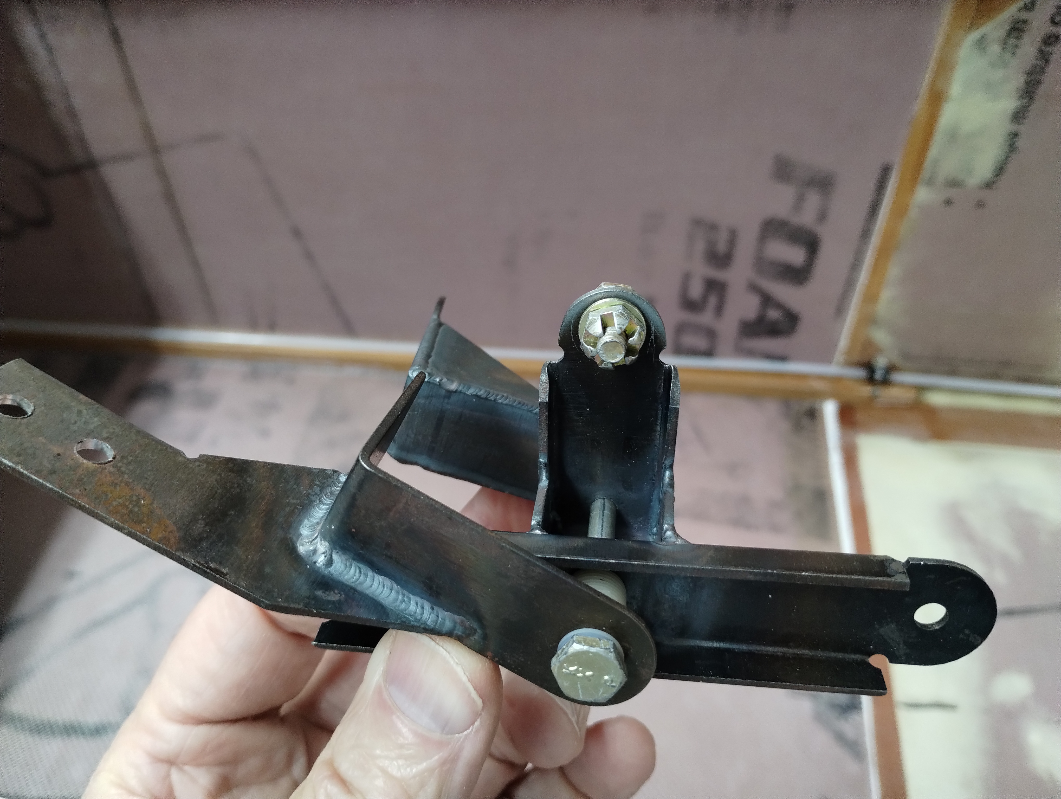
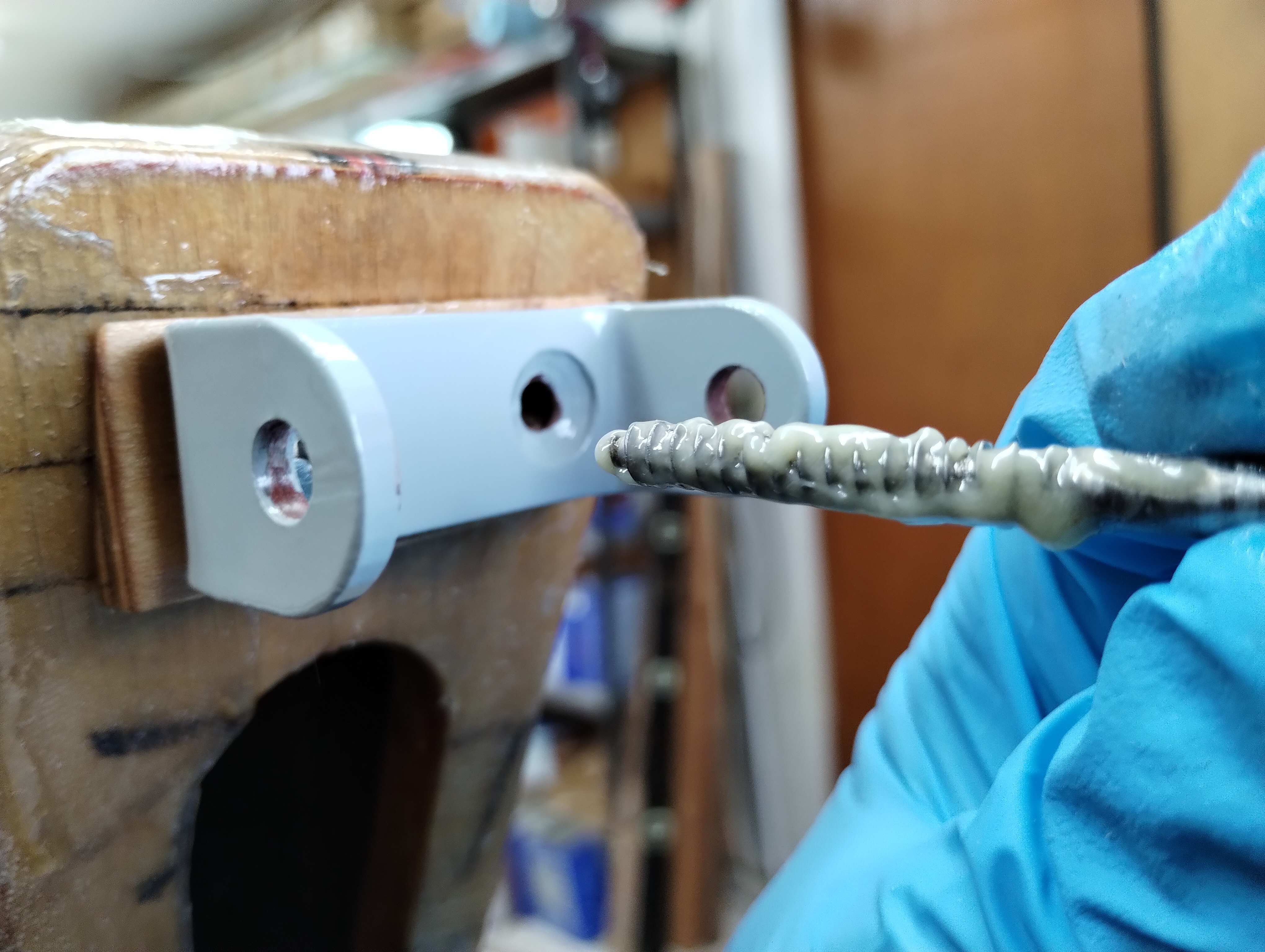
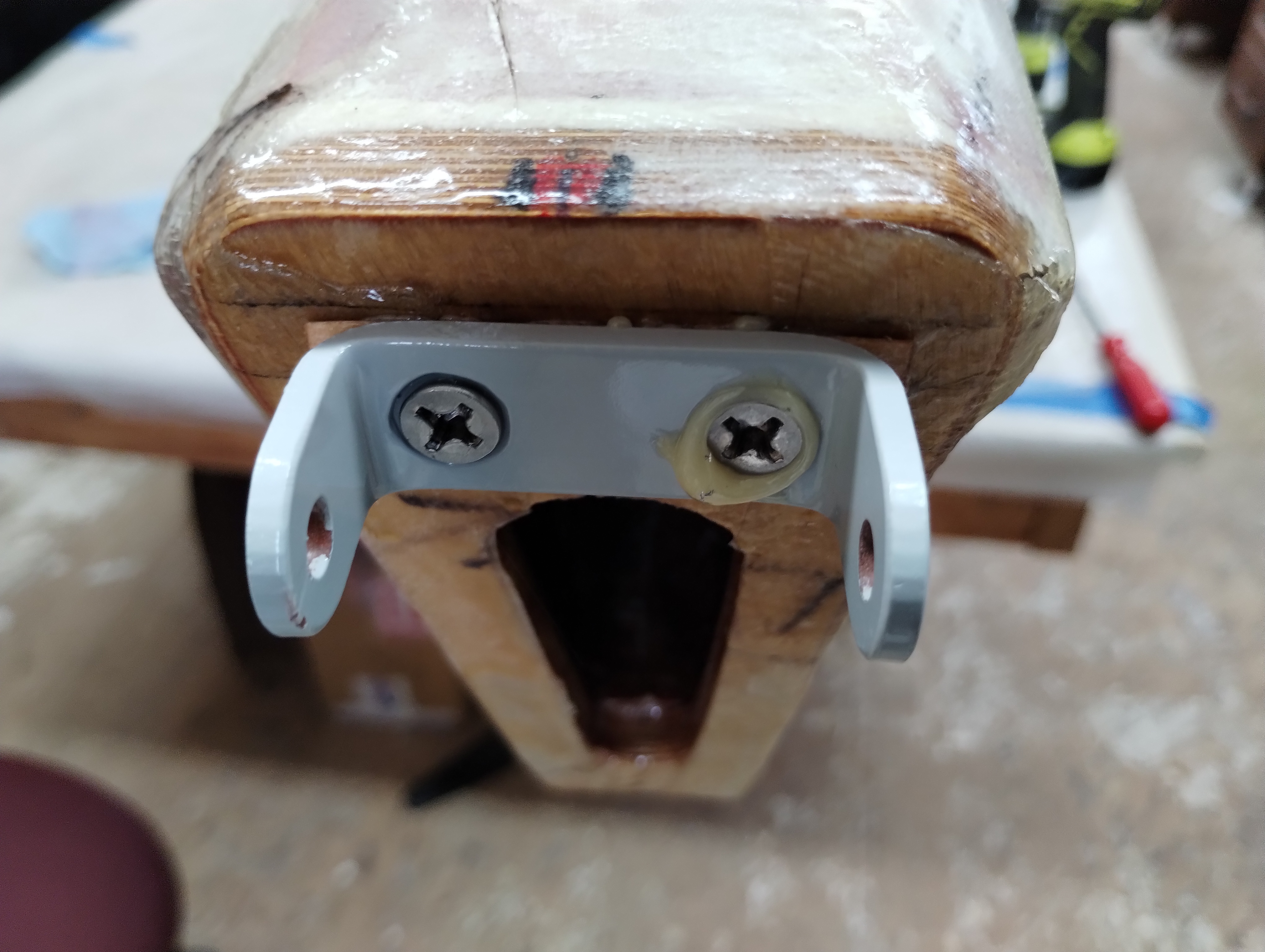
Then mount the elevator hinge pivot bracket. These screws go through the plywood tail plate and into the longerons. Lots of wood to bite into and hold.
Liberally apply T88 epoxy resin to the screw holes and threads. Don't want
this bracket to move. Ever.
Finally, complete the exterior cabin-to-empennage exterior splice bands
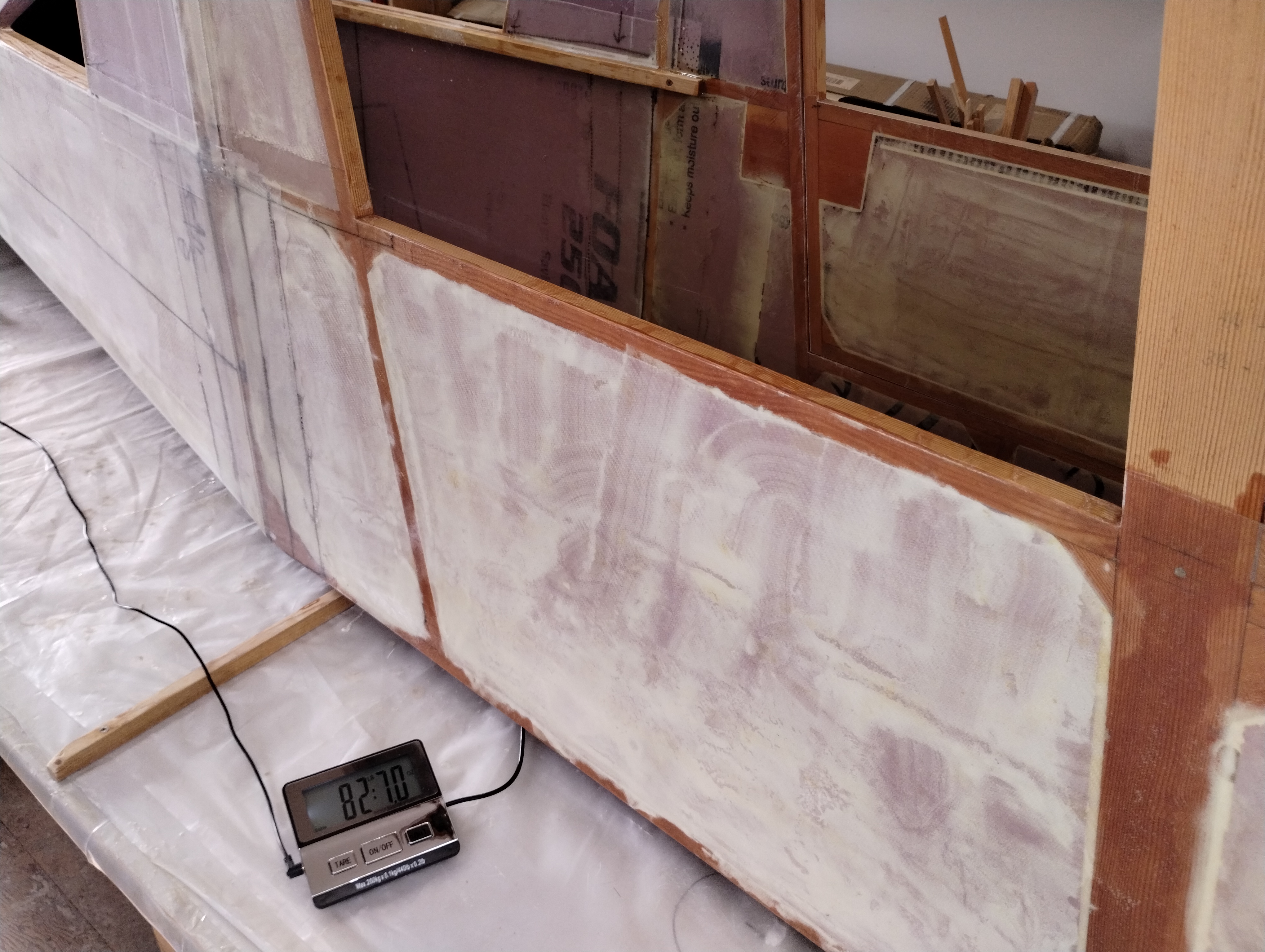
Weight with the door clipped into position comes in at just under 83 pounds.
Oscar's with a bit more finish is about 3 pounds lighter. No data from Marvin's
build so it'll have to do.
Done enough for now. It's time to start in on the
tail feathers while I've got the XPS shaping and fibreglass mode firmly going.