Bou's M-19 Project
Flying edition construction
20200217- 20200225 Many project related, non-construction tasks undertaken;
- Garage-saled wood-working tools - 10" table saw, 11" band saw and 6" x
48" - 9" disk sander. Spent the next day tuning and adjusting tools and
ordered sanding media
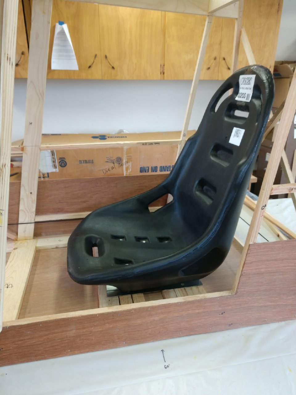
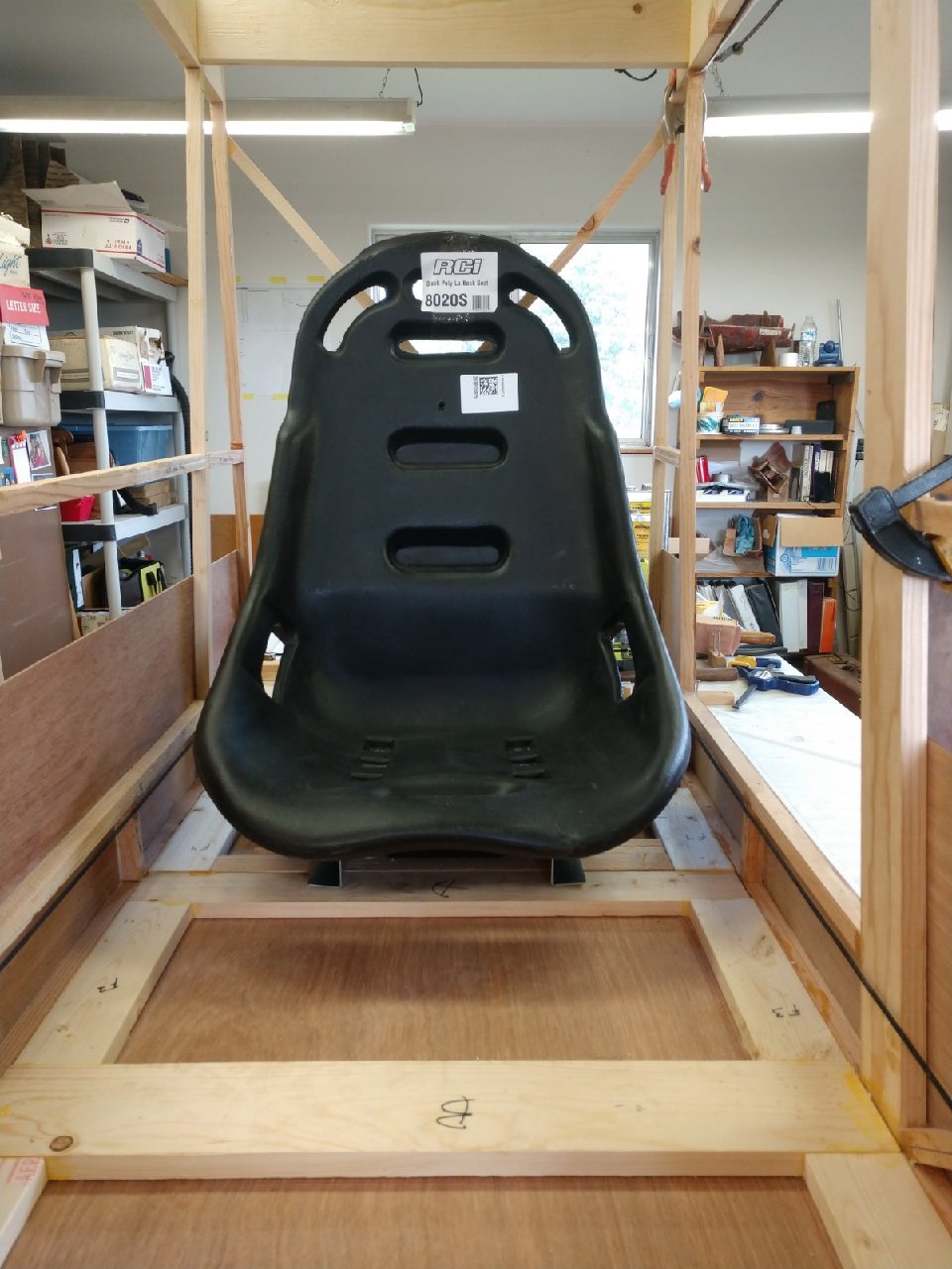
- Researching commercially available poly race car seats, finally ordered
RCI 8020S Poly Baja Lwbck Seat Blk
- Locating local suppliers of Western Hemlock lumber
- Elusive search for Dow Styrofoam Brand Residential Sheathing in 3/4" x
4' x 8" sheets. Finally tracked down a lead for Owens Corning Formular 250
XPS Rigid Insulation in the same size. Awaiting final pricing and shipping
details
- Also converted Marvin's Parts list to an Excel spreadsheet to simplify
getting total counts of all materials and ordering items
20200229- Leap Day! Began assembling Construction Manual into 2 volumes;
V1=new digitized text document &
V2=original diagrams and CAD dimensions
20200305- place OC Formular 250 3/4" Square Edge order for 15 sheets with Kaz
@ Service Partners/ Tigard
- RCI seat arrived today and plopped it into the mock-up cabin; looks like it might work.
20200306- build cross-reference for parts list to drawings callout
- Called John Pike of Big Sky Stearman; told him I bought spruce for my KR2S from Claude,
his dad in the 1990s; sent email for quote
20200307- requested sheet steel quote from Metal Supermarkets Portland
https://www.metalsupermarkets.com/portland
20200308- received quote @ 161.79
20200309- called HIO FSDO re: if a plans review is recommended prior to buying
materials
- requested sheet steel quote from West Coast Metals http://www.westcoastmet.com
- requested sheet steel quote from https://www.standardsteelnw.com/
- Keith Ruconich/ HIO FSDO called and confirmed no plans review required; work with Gary
Brown again; "Good Luck!"
20200322- placed 4130 order from Josh @ ACS
20200323- added 9x9x.250-4130 to ACS order
- placed initial composite products order from ACS
20200324- created CAD
drawing for #2 Rudder Pedal
20200325- submitted RFQ to Wicks for parts
20200330- Cut to fit firewall & instrument panel; laminated 2 scraps of 6.5mm
plywood to form 1/2"
blanks for aileron horn plates and tail plate;
laminated 2 pieces of 1/4" plywood to form 1/2" blank
for spring plate
20200331- cleaned up shop; rough cut tail plate
20200401- picked up foam at Service Partners; stored in shop; now I just need
wood!
20200402- CAD drawing for #9 Bottom Bellcrank and #10 Lower Aileron Pulley
brackets; ordered new band saw blade
20200403- Finished #55 Aileron Horn Mount Block & #82 Tail Plate fabrication;
cut nose rib pattern template
Waste not, want not. I laminated plywood "scraps" from an earlier KR2 firewall
replacement remnants to make required dimensional stock.
Hand cutting to minimize the kerf let me get both horn mounts from a tiny piece
of material.
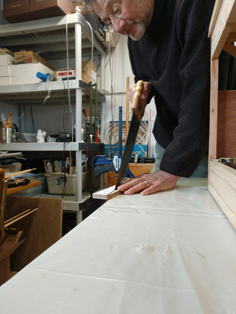
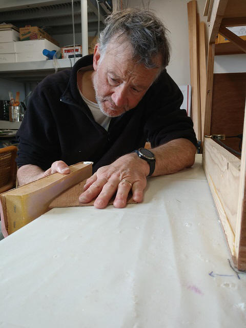
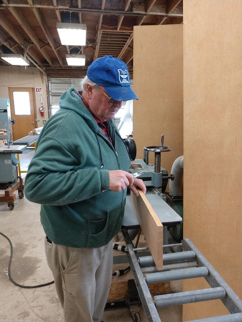
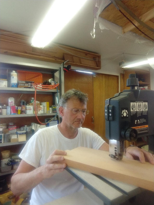
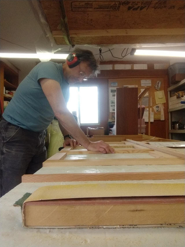
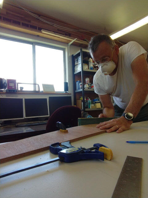
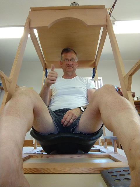
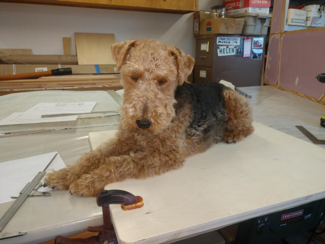
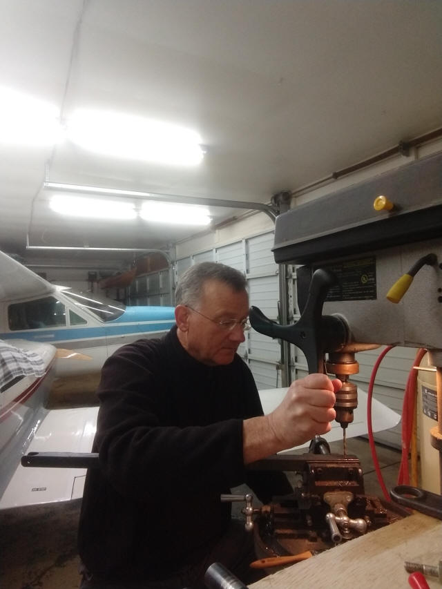
Sorry about all the photos of me.
With the FAA Repairman's Certificate in mind, I must document who is
actually building this airplane...
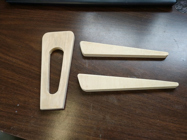
Count those plies!
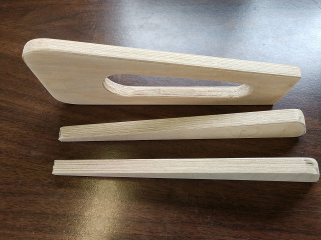
Yeah, you're right, 13mm & 20 plies...
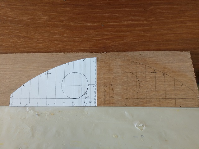
20200404- used acetone to transfer nose rib pattern to plywood template,
cool!
Pretty simple actually. Print diagrams with a laser printer. Trim to size and
lay image side to material. Saturate a cotton ball/ paper towel with acetone and
rub the back side of the printed image firmly onto the material. Carefully peel
it off and the reverse image is transferred to your material.
--UPDATED-- I found out it is better to apply acetone with an acid brush. Ink
transfer works better with a tongue depressor cut to a blunt straight edge. It
"pushes the ink" onto the material.
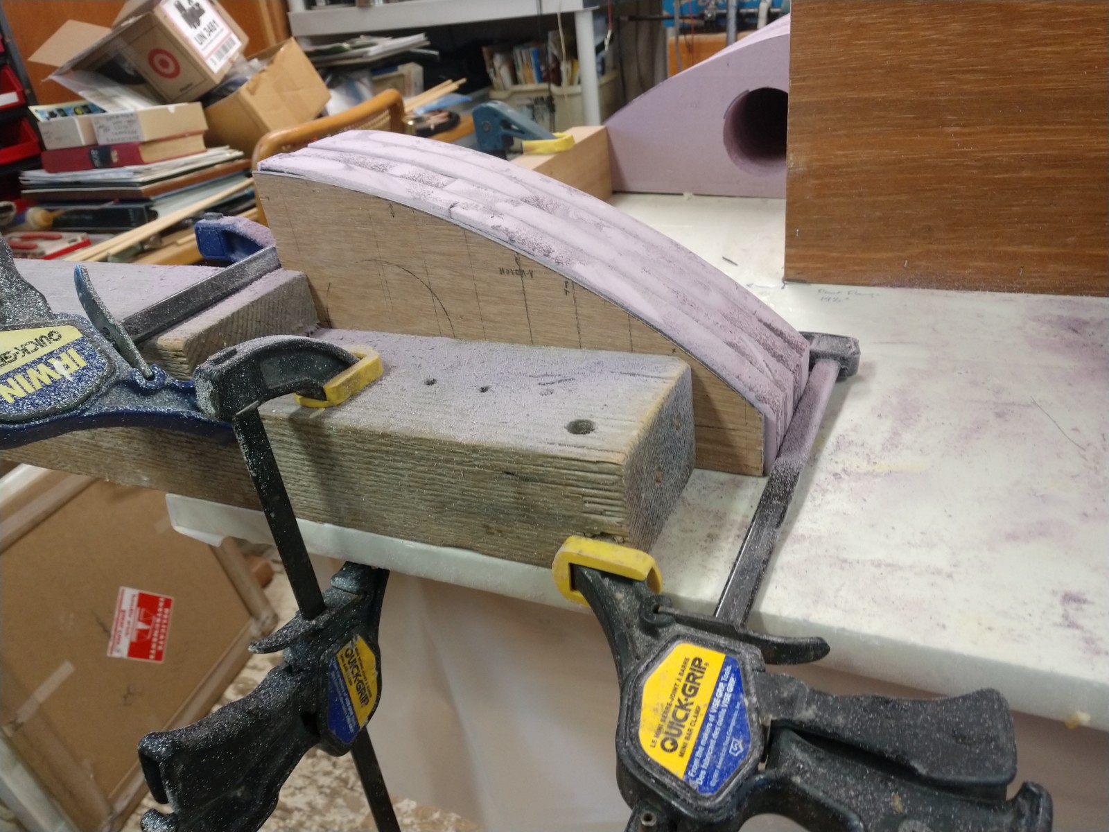
Cut & trimmed to final shape
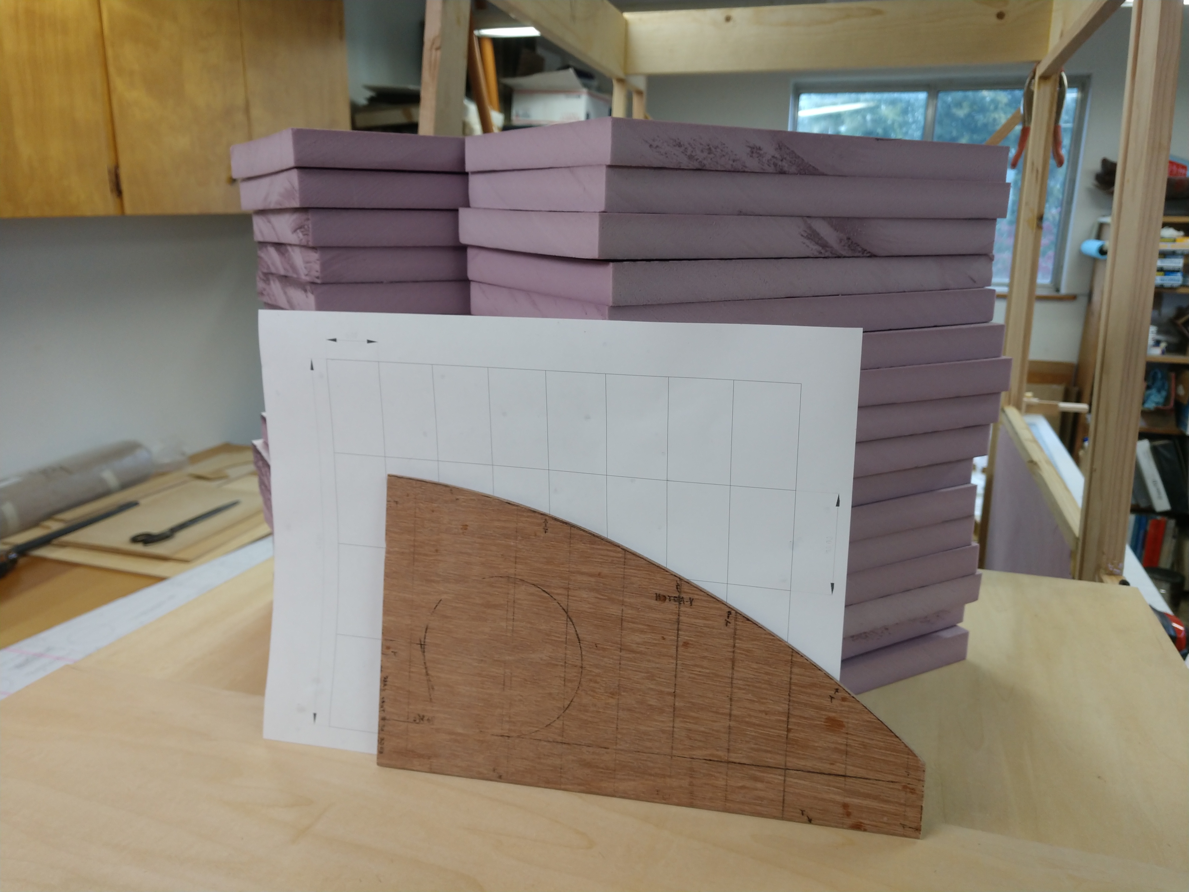
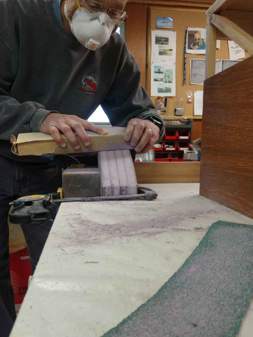
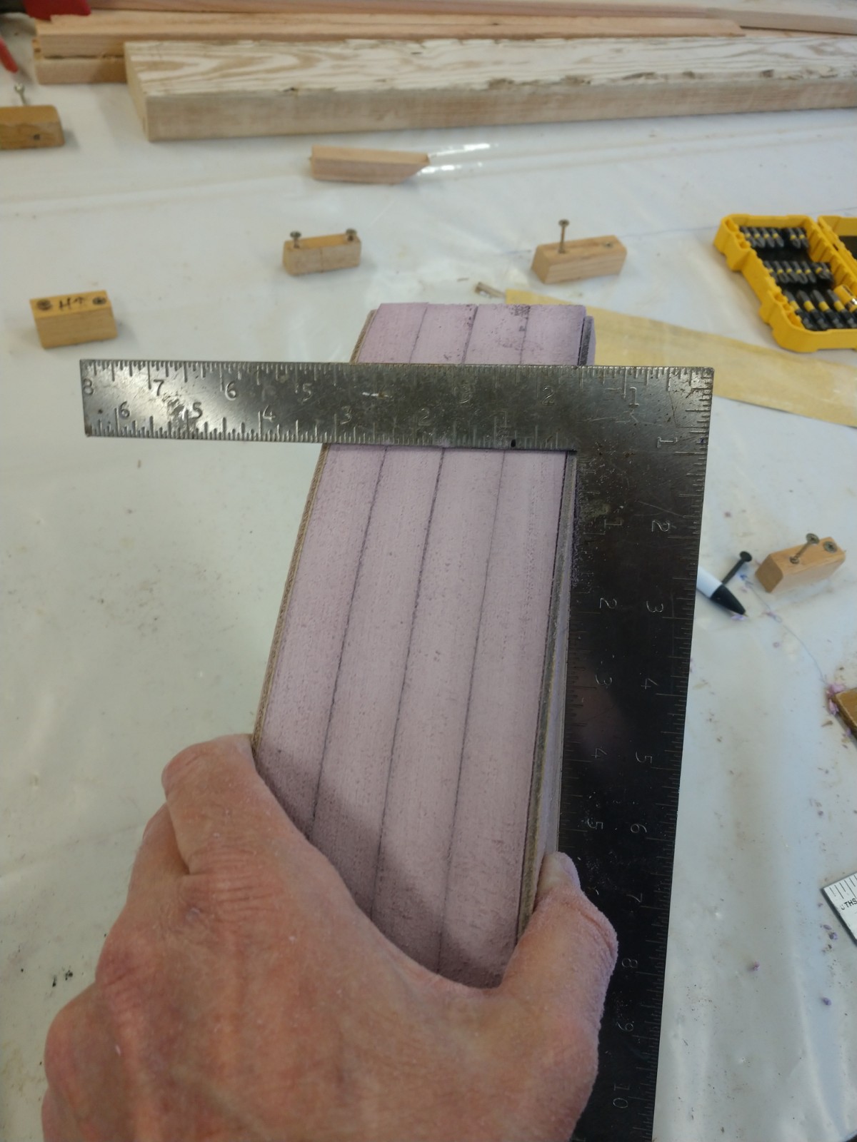
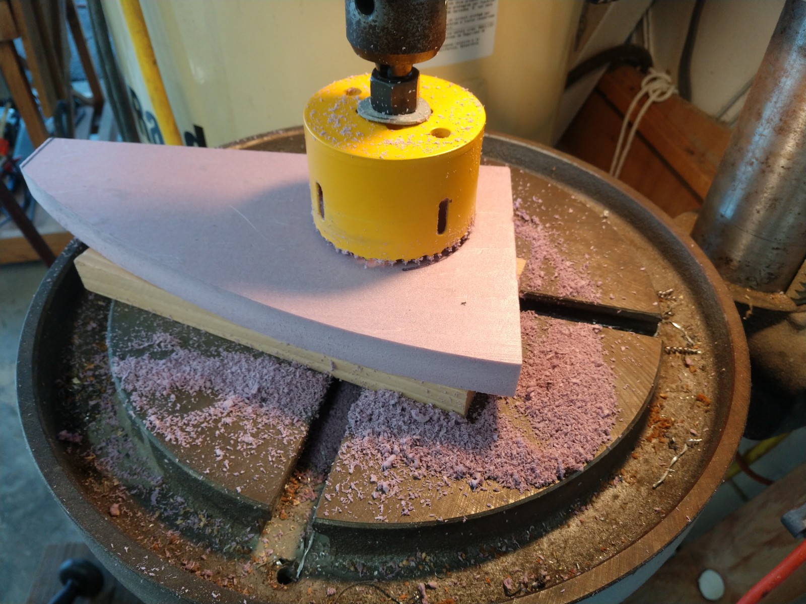
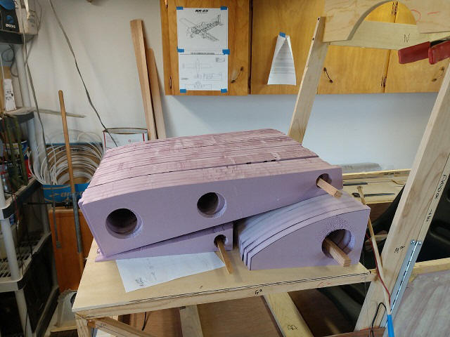
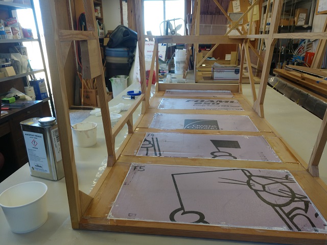
20200405- cut 1st XPS sheet to 40x48; blocked to 6"x10"; laid out template
line, rough cut on table saw, sanded to line on disk sander, jigged with 2 wood
templates and sanded to consistent size; cut 3" lightening holes on drill
press; all 32 done took almost all day + 45 minutes with the shop vac. Gotta be
a faster way...

Jump to Hot Wire Rib Cutting page
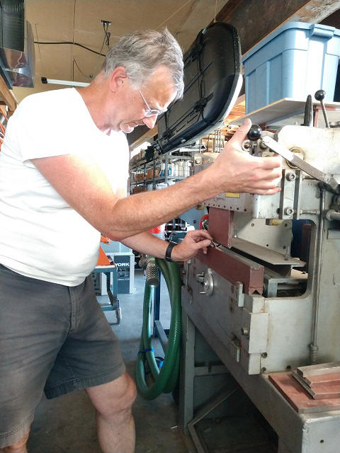
20200409-12 Actually got some flying in, cleaned up shop, mounted & rewired
my mid-60s belt & disc sander & motor
20200413- Remade trailing ribs to higher standard
2020415-19 More CAD drawings; Thank you Neal!
20200425- picked out wood for cab structure with John Pike at Big Sky Stearman
20200426- ripped wood to dimension for cab layout. Turns out I was a few
pieces short...
20200427- picked up remaining wood for cab structure at Big Sky Stearman
20200429- ripped to final dimensions
20200430- rough chop cut to individual lengths
Oscar helped me visualize how the parts come together. Thanks Oscar!

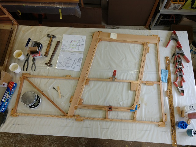
Side 1 Layup
Side 2 Layup - Door side - still not positive if it going to be on the Left
or Right; thinking it's the left...
20200504- Door layup complete. I used 0.041 stainless safety wire as my
spacers instead of the credit cards Marvin used.
Note oversize gusset blocks for hinge mounting and the door latch.
I haven't yet decided about the armrests Oscar installed but I think some
structure adjacent to the seat would be a good idea.
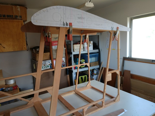
Tomorrow, I get to remove the guide blocks from the table and stand up the
frames. Yay, 3 dimensional project!
Cut the forward carry-through spar
Cut and fit the floor members
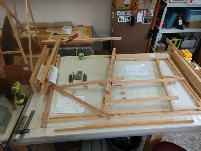
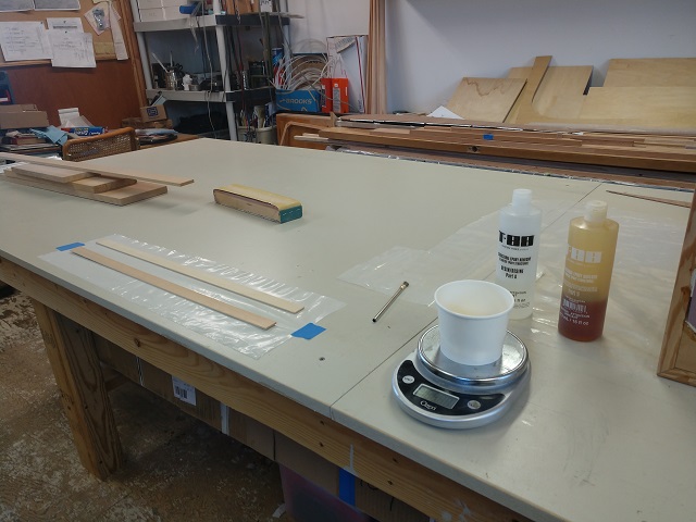
Start by making a straight base line for the forward fuselage point. I
wrapped S4S spruce members with wax paper and clamped them into place
aligned with the table end. Then place
one row of guide blocks on the table surface at 90 degrees to the firewall. Next
place another row of guide blocks 25 1/2" away to keep the sides parallel and
properly spaced. I used wedge blocks for the flooring clamps. This is a critical
step as all alignments are derived from a square and true cabin structure. Tip:
Mark your spar locations now while you aren't rushed.
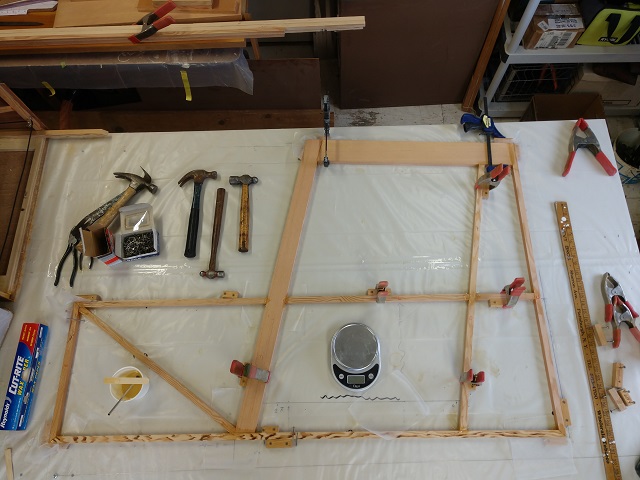
Now that everything is cut and dry-fit, practice your assembly sequence.
There won't be time to muck about after you mix the glue.
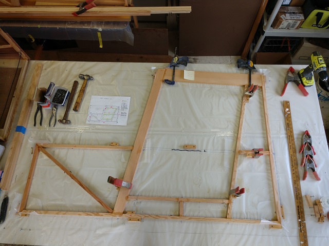
Finally, it's go time! Erect the sides, glue up the floor members
and carry-through spars. Use carpenter squares to assure the sides are square to
the table and each other. I used bicycle tubes as clamps for the spar-to-side
rail glue joint.
I used 2 batches of T-88 epoxy (about 100g) each to extend work time. There
is a considerable amount of surface area to coat; all 60" of both 3/4" inner
side frames, the adjoining longitudinal members, the ends of all the
cross-members, the firewall structure members and gussets and, oh yes, the spars.
A disposable chip brush helped spread the glue quickly. Go go go...
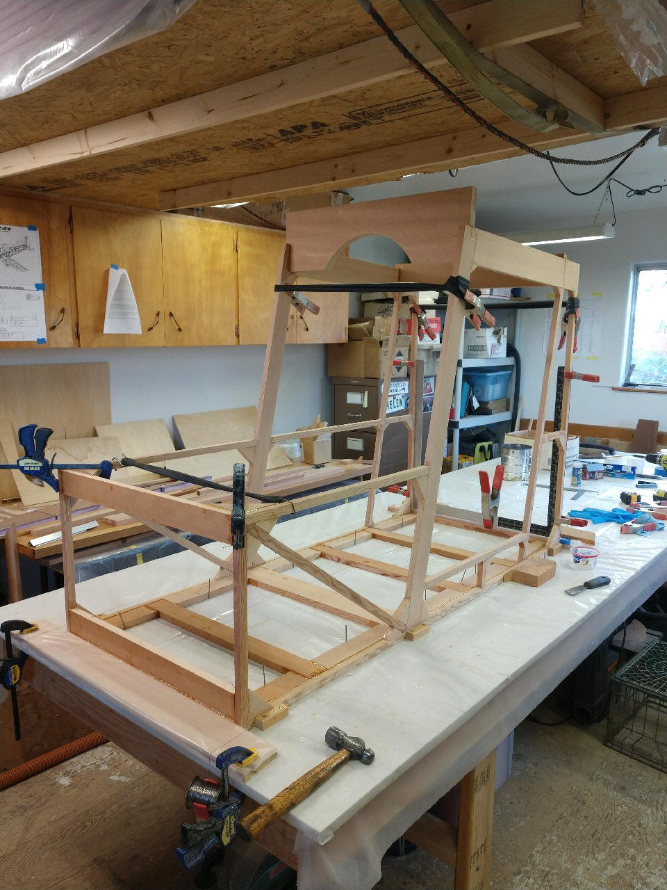
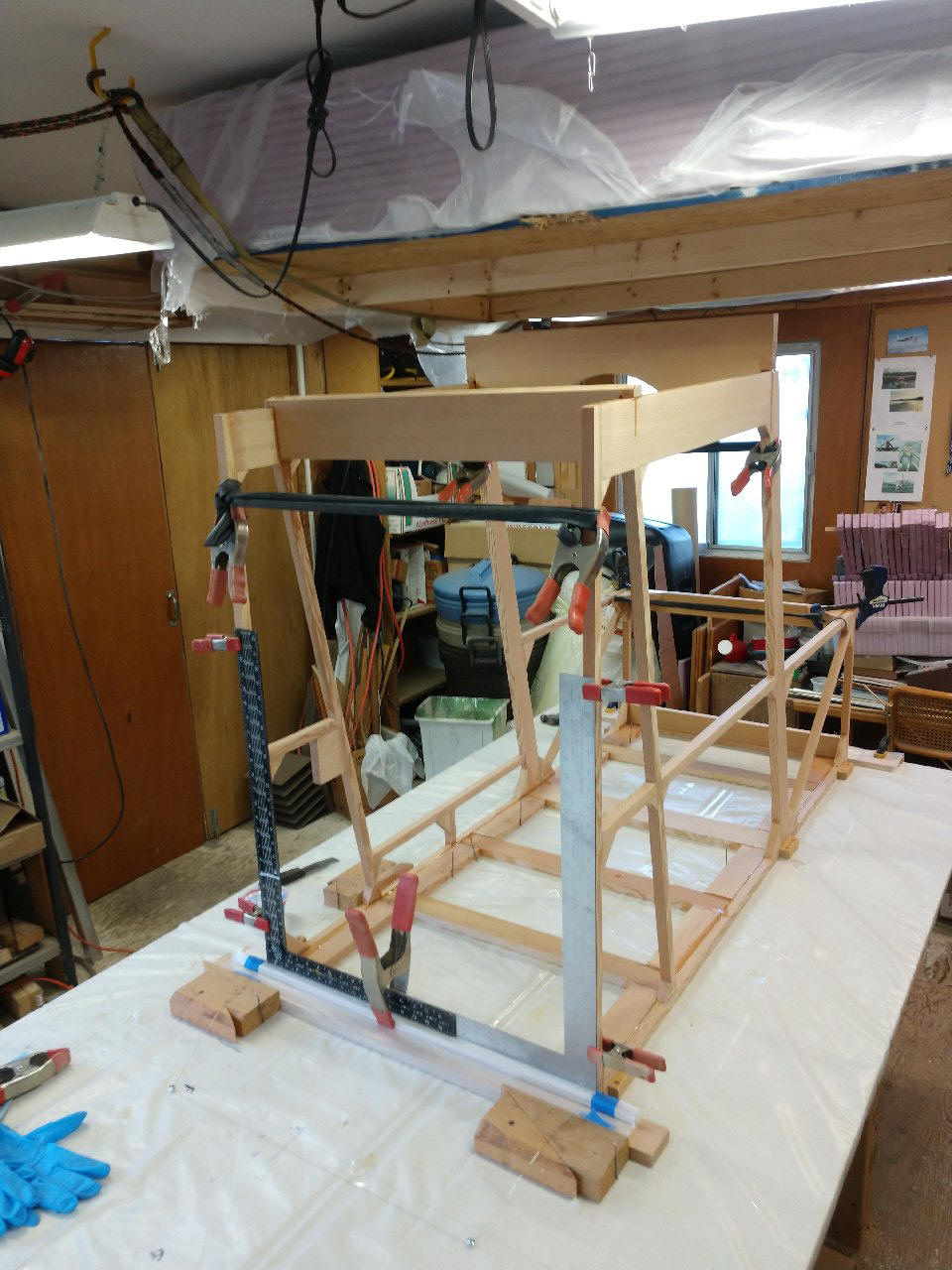
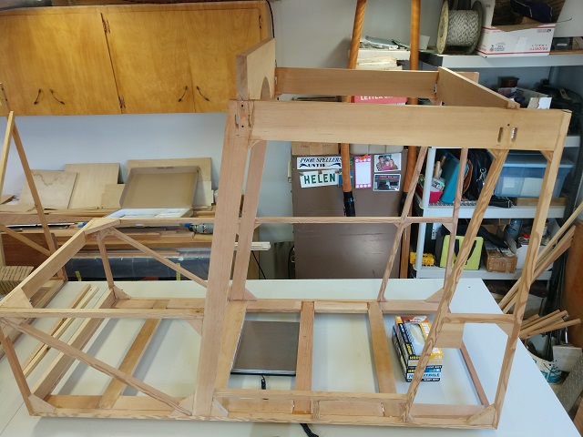
My resulting cabin build. I'm happy with this.
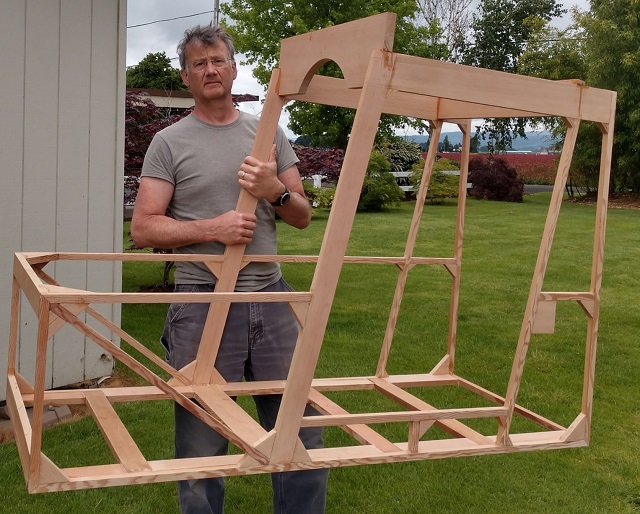
I'm getting to the point where I now need the metal parts. Next step is to fit
the carry-through spar Wing Attach Fittings (WAF) to the cab frame.
Actually I
need to install the structural screws into the wing chord "N" rails and spars.
It's tight for clearance so I've switched over to practicing on my
mock-up.
Jump to MetalWorking page...
Getting all the parts together to drill the carry through spars includes
having the wing chord plates done; check
20200708- Catalog all my AN hardware into a storage drawer bin.
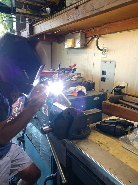
20200714- Worked in Cal's shop trimming, bending and shaping metal parts
And Cal welded my rudder pedals
20200719- Finally tried on the cabin for size; just right!
20200721- Cut through the chord rails. I was concerned about this step as an
error here would be catastrophic. It turned out to be just another building
step.
Since I made CAD drawings for all the metal parts, printing them as templates
for layout seemed a good idea.
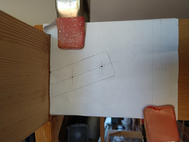
Transfer the cut lines and score them to avoid splintering the chord rail. Drill
through.
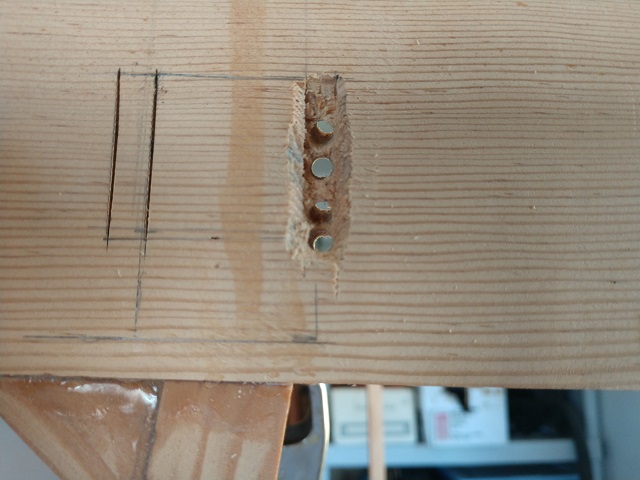
Connect the dots and clean up the slots. Insert the WAFs & drill the
fastener holes. Done. Repeat...
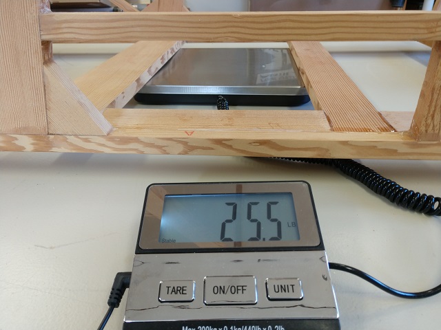
20200725- Data point. 25.5# bare Doug Fir structure.
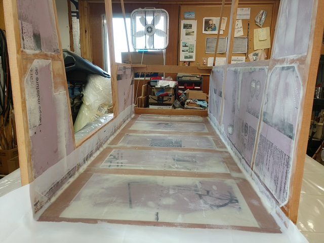
20200725- Cab floor XPS panels installed
Then my camera screwed up and I couldn't get any photos. From the 25th &
30th, I installed the remaining XPS panels into the cab frame and filled gaps
between the wood & XPS panels.
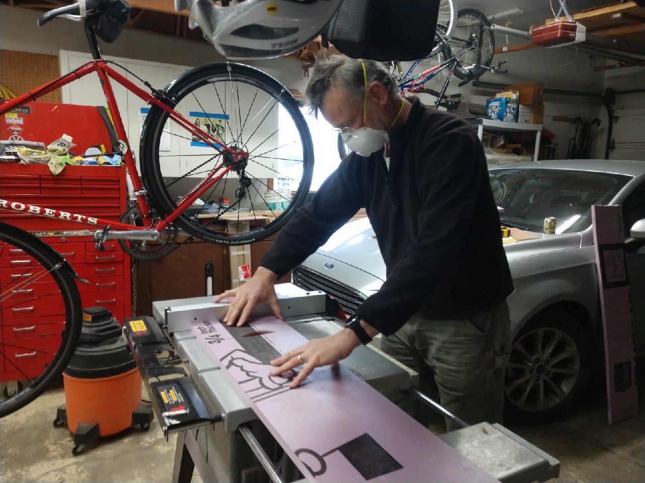
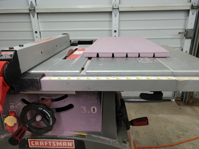
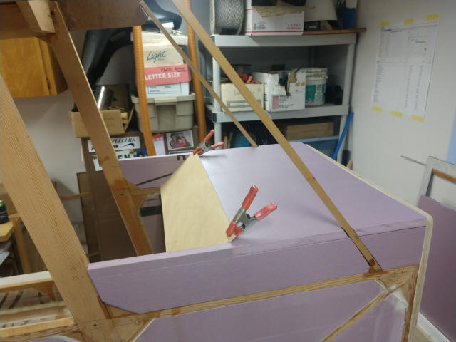
20200730- I cut the XPS panels to fit the roof forward and center sections. The
manual says to use a knife to cut slots almost full depth allowing the panels to
conform to the upper airfoil profile. I figured I'd slip and cut all the way
through the panel. I used my table saw with the blade set to
10 degrees and ran the XPS panel through. Then I reset the fence to the other
side of the blade and reversed the
XPS foam's direction to complete the 20 degree notch. It DID make a heck of mess
as evidenced by the face of the table saw...
I made an error interpreting the drawings of the wing chord plate and set the
position 1/8" too high. With 40G of T-88 epoxy, there's no removing the chord
plates. I conferred with Oscar and decided to laminate a strip of spruce to the
top of the wing center spar carry throughs.

20200802- Moved the cab to the hangar to get the exterior bottom skin at
working height. Finished filling gaps with micro. Sanded smooth.
Cleaned and organized the shop for fibreglass work.
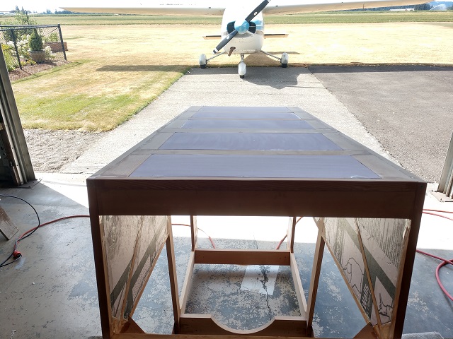
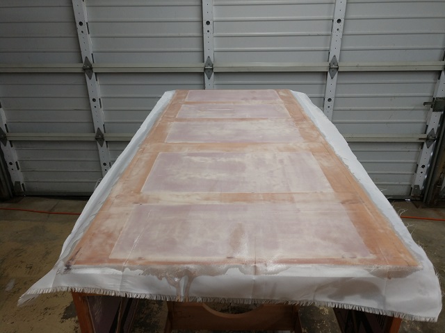
20200803- Skinned the exterior bottom skin with
Hexcel 7725 BID 8.8 oz cloth &
AeroPoxy PR2032 resin and PH3660 hardener
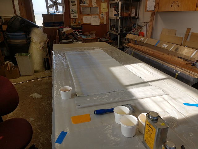
I followed along with what
Mark Langford taught the
KR builders about using a
sheet of plastic
(his site explains ALL!) to template the required fibreglass cloth size. Bonus
is that it gives you a working surface to wet out the cloth with resin and then
to move it into precisely the correct spot before fixing the final location.
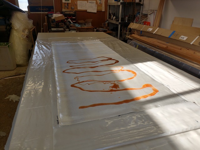
Layup transferred and squeegeed into place with transfer plastic sheeting
removed
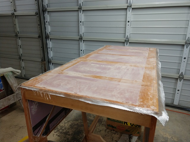
Applied Peel Ply
20200806- 08 Cabin interior prep for glass; fill dents & seam gaps, rough
sand & repeat; pour fillets between floor & cabin sides

20200809- finish sand cabin interior
20200810- lay out materials; too warm to use epoxy already @ 9am
20200811- Lay up cabin floor 1:34 elapsed time about 500G resin
20200813- Layup Right side cabin wall interior
20200814- Layup Left side cabin wall interior
20200815- Trim and sand glass flashing; place outdoors in 103 degree sunny
day to aid (post) curing
rough located main landing gear structure, rudder pedals & seat

20200816- Get measurements for fabricating MLG & wing strut carry thru
channels
20200817- Metal work on wing strut carry thru channel
20200819- Redesign WSCT to use 4130 box section tube with reinforcing bolt
hole webs weldments
20201027- No excuses for time passing. Got shed shop reorganized to start up
again.
Next steps:
Drill the cabin area for rudder pedals, MLG brackets & strut attachments for MLG
& wing struts
Install the firewall, forward deck foam, instrument panel & roof foam. Then
glass the exterior.
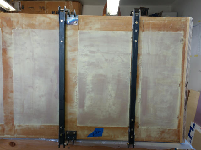
This is my helper making sure the firewall plywood doesn't slip on the work
bench. Thanks pal, now move so I can get something done...
T88 mixed with micro-glass fibres (to increase bonding ability) into a
slurry. This resists running off the surface prior to making the wet connection
to the fuselage cross & vertical members.

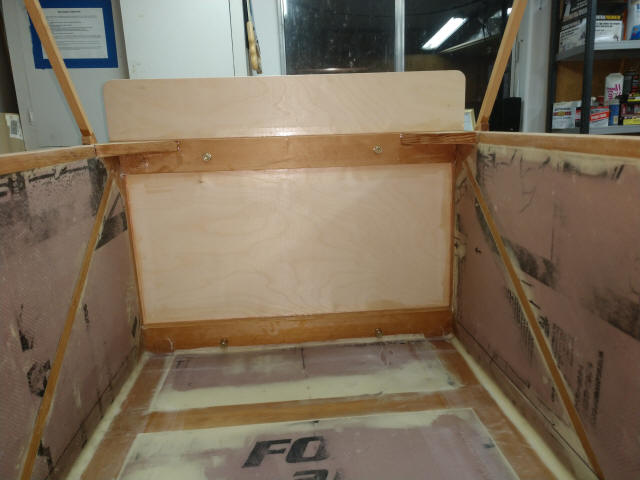
Lay out the cabin structural gussets.
Then install the carry through steel tubes. Reminder: the channels were bent
without a proper 1/8" radius allowance. And they cracked...
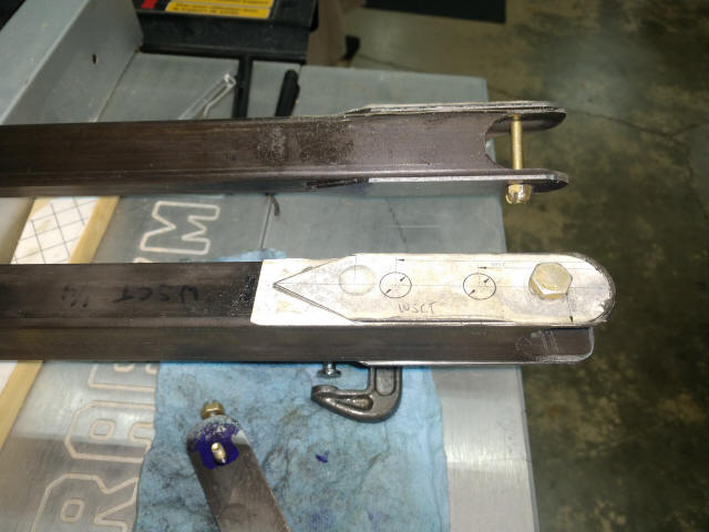
So we redesigned these to use 1"x1"x.065" 4130 steel tube with 1"x.065" 4130
steel doubler plates welded on, giving both sides the 1/8" thick bolt bearing
surface to carry the loads.
Even though I used LibreCAD to lay out the placement, I didn't see this
coming.
So I'll get to remake the WSCT tube enough longer to clearance the bolt heads.
Yeah, ok, I'm still a novice builder...
Part of the M-19 design is foldable wings so these bolts have to be
removable. Best practice says bolt heads should always be forward. This doesn't
always work out as practical. Case in point: engine mount bolts; these run
through the firewall and to install cotter pins or even check that they are
still present, you have to be able to see them. That's only practical under the
engine cowl so those bolts have to run with the nuts on the forward side. And
even Cessna does it this way...
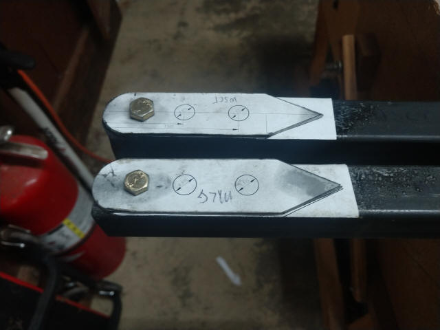
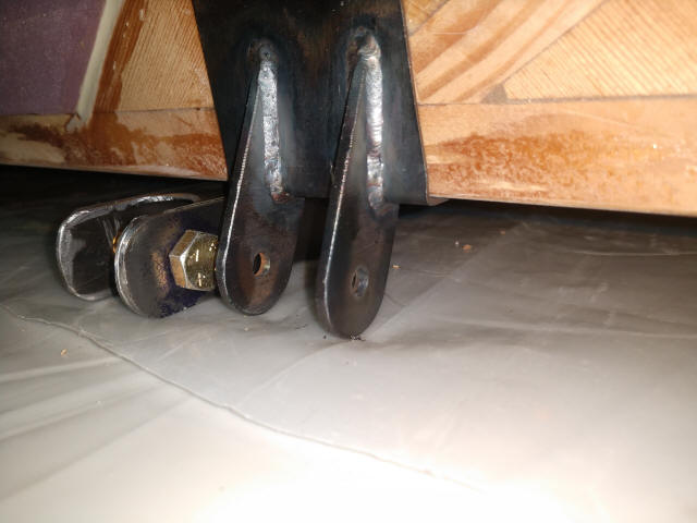
Finally everything is in place (with the disclaimer I get to remake the tube
referenced just above...)
*The tube on the left is the WSCT and has 2 AN3 heads exposed to anchor the
cabin structural gussets.
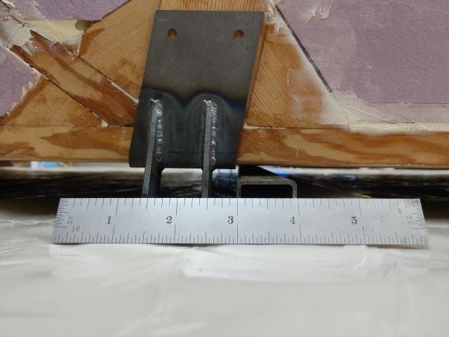
*The tube on the right is the MLG forward pivot mount and has 4 AN3 heads
exposed to anchor the rudder pedals.
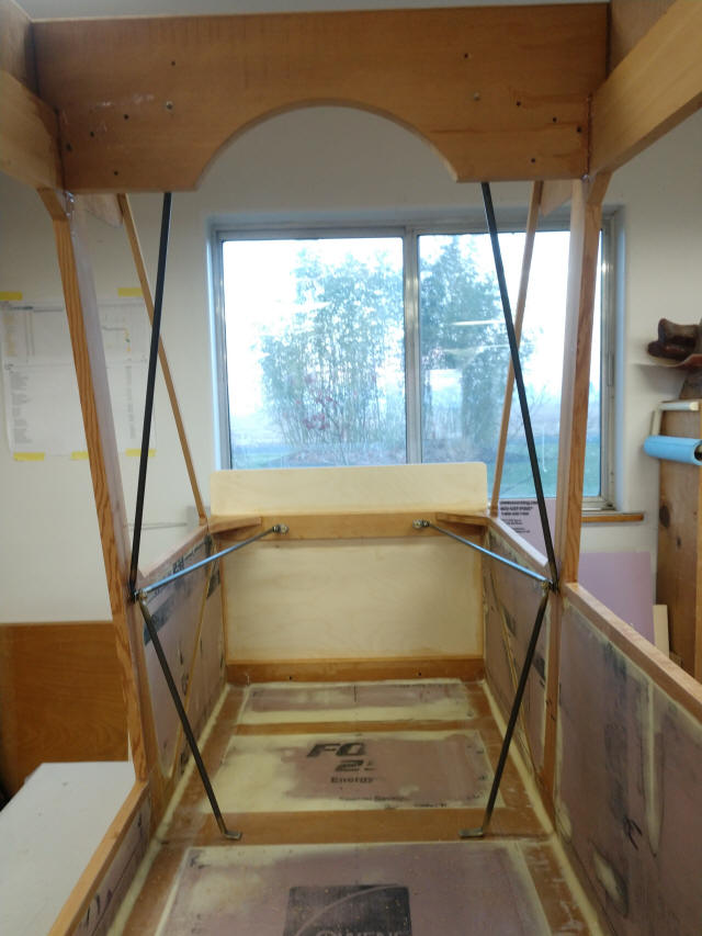
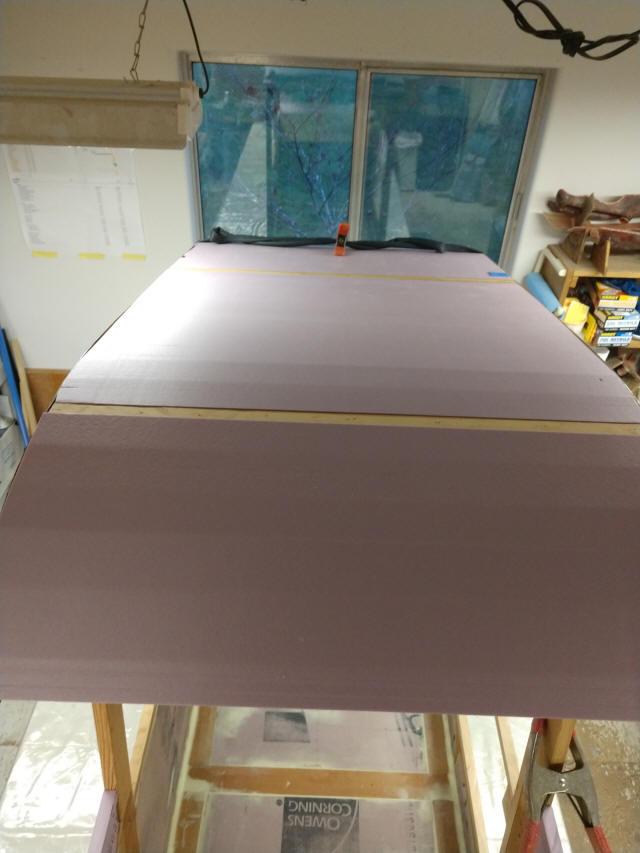
With the floor holes now drilled and fitted, it's on to finishing the cabin
with getting the cowl deck, instrument panel blank and
roof panels into place in preparation for the exterior fiberglass.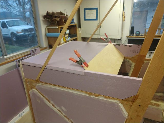
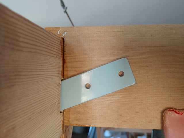
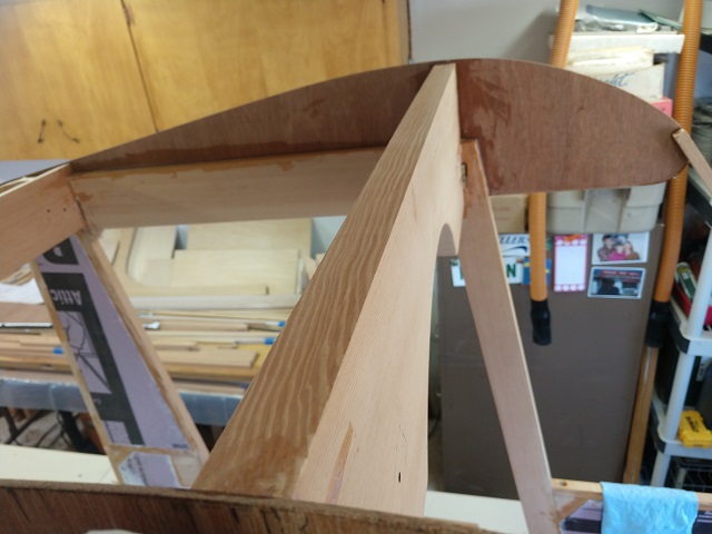
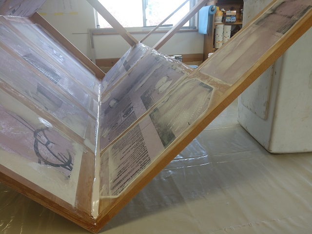
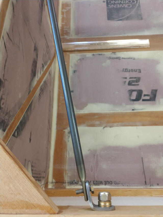
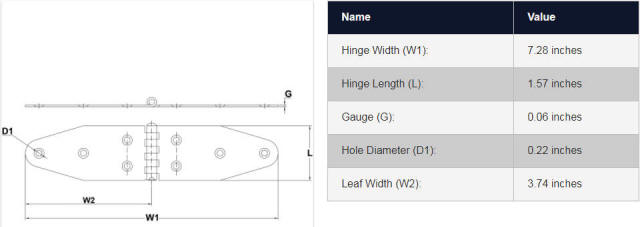
Getting ready to hinge the door with these;
https://www.e-rigging.com/_p_7976.html
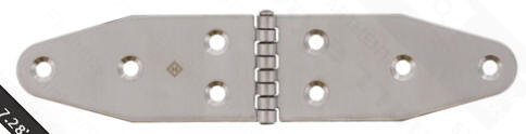
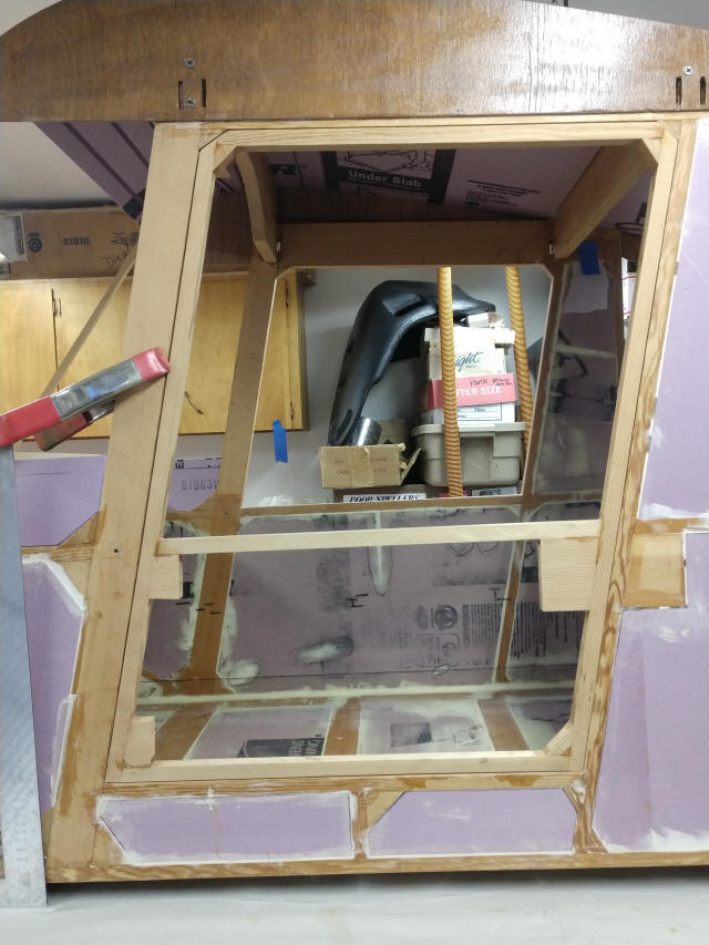
The Square is in place to help visualize the hinge pin alignments. Oscar pointed
out if the hinges are aligned with the frame, the door will swing up and into
the wing. No bueno. So the hinge pins have to be vertical & the upper hinge must
be offset forward. Hmmn, funny, just like Marvin drew it in the plans on Page 64
of the Draeings book . Duuh. Thank you Marvin.
If I'd just pick up on all these fine details without bugging OZ maybe he'd be
flying by now...